32
42PD9700C/U & 55PD9700C/U
Item
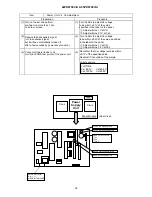
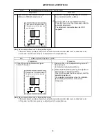
Power Unit Vs, Va Adjustment
Preparation
Procedure
(1) Turn on the set and perform
pre-heat run more than 1 min
on burn-in screen.
(1) Turn Vs ADJ to adjust Vs voltage
to be within ±0.1V of the value
specified in the label on the panel.
Adjust within ± 1V at Vs1
Adjust within ± 0.1V at Vs2
(2) Receive full back pattern signal
(or Video silence signal;
but it will be automatically turned off
after a few seconds by power save function.)
(2) Turn Va ADJ to adjust Va voltage
to be within ±0.2V of the value specified
in the label on the panel.
Adjust within ± 1V at Va1
Adjust within ± 0.2V at Va2
(3) Connect voltmeter leads to Vs
(or Va) and GND test points of the power unit.
(3)
Label example
<LOT>N6
Vs= 80.0V Va=60.0V
Vw=140.0V Vx=60.0V
Pow e r
Supply
Unit
X-sus
Y-sus
(Rear View)
Panel Module
Label
Reconfirm that Vs voltage remains within
±0.1V of the specified value.
Readjust if it’s outside of the margin.
n
i
P
t
s
e
T
a
V
/
s
V
9
9
N
C
s
V
a
V
D
N
G
5Q
1
4
7
F
P
M
a
t
a
r
u
M
*
*
*
*
*
*
*
*
N
/
S
MADE IN THAILAND
R
V
t
n
e
m
t
s
u
j
d
a
e
s
r
a
o
c
s
V
:
1
s
V
R
V
t
n
e
m
t
s
u
j
d
a
e
n
i
f
s
V
:
2
s
V
R
V
t
n
e
m
t
s
u
j
d
a
e
n
i
f
a
V
:
2
a
V
R
V
t
n
e
m
t
s
u
j
d
a
e
s
r
a
o
c
a
V
:
1
a
V
Summary of Contents for 42PD9700C
Page 58: ...SM 011 POWER BOARD CIRCUIT SHEET 1 ...
Page 59: ...SM 011 POWER BOARD CIRCUIT SHEET 2 ...
Page 60: ...SM 011 POWER BOARD CIRCUIT SHEET 3 ...
Page 61: ...SM 011 POWER BOARD CIRCUIT SHEET 4 ...
Page 62: ...SM 011 POWER BOARD CIRCUIT SHEET 5 ...
Page 63: ...SM 011 MAIN BOARD CIRCUIT SHEET 1 ...
Page 64: ...SM 011 MAIN BOARD CIRCUIT SHEET 2 A WAKE UP MAIN 5 ...
Page 65: ...SM 011 MAIN BOARD CIRCUIT SHEET 3 ...
Page 66: ...SM 011 MAIN BOARD CIRCUIT SHEET 4 ...
Page 67: ...SM 011 MAIN BOARD CIRCUIT SHEET 5 MAIN 2 ...
Page 69: ...SM 011 SUB POWER BOARD CIRCUIT ...
Page 70: ...SM 011 CONTROL BOARD CIRCUIT ...
Page 71: ...SM 011 SOUND BOARD CIRCUIT ...
Page 74: ...SM 011 FC BOARD CIRCUIT SHEET 3 ...
Page 75: ...SM 011 FC BOARD CIRCUIT SHEET 4 about 7mA It is 0 4V at 22V to in press it ...
Page 76: ...SM 011 FC BOARD CIRCUIT SHEET 5 Female BM VIDEO change To IC202ARGB AMP ...
Page 78: ...SM 011 FC BOARD CIRCUIT SHEET 7 A B work C D work A B work C D work ...
Page 79: ...SM 011 FC BOARD CIRCUIT SHEET 8 ...
Page 80: ...SM 011 FC BOARD CIRCUIT SHEET 9 MAIN µ com ...
Page 81: ...SM 011 POWER BOARD ...
Page 82: ...SM 011 MAIN BOARD COMPONENT TOP SIDE ...
Page 83: ...SM 011 MAIN BOARD SOLDER BOTTOM SIDE ...
Page 85: ...SM 011 FC BOARD SOLDER BOTTOM SIDE COMPONENT TOP SIDE ...
Page 90: ...SM 011 WIRING ASSEMBLY DIAGRAM 1 ...
Page 91: ...SM 011 WIRING ASSEMBLY DIAGRAM 2 ...
Page 92: ...SM 011 WIRING ASSEMBLY DIAGRAM 3 ...
Page 93: ...SM 011 ASSEMBLY DIAGRAM ...
Page 95: ...THE UPDATED PARTS LIST FOR THIS MODEL IS AVAILABLE ON ESTA ...


