53
42PD9700C/U & 55PD9700C/U
8. Self-Diagnosis Function
This chassis has 2 modes of self-diagnosis function.
(1)
PDP panel check mode: It indicates the one latest record of the PDP panel failure with blinking of the
power indication light (LED).
(2)
Signal circuit check mode: It indicates the check result on some points of the signal circuit and the history
of them with On-Screen Display (OSD).
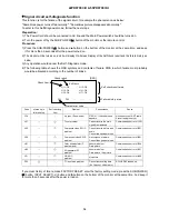
PDP panel self-diagnosis function
This function is for a PDP panel failure with no picture.
To enter to this Self-Diagnosis mode, follow the next steps:
Preparation:
1) The Power Cord should be connected to AC line and the Main Power switch should be turned on.
2) Turn the power off by the SUB-POWER( ) button of the monitor or the remote control.
Procedure:
1) Press the SUB-POWER( ) button and button on the bottom of the monitor at the same time, and keep
it for more than 5 seconds after the power turned on.
2) It generates red blinking series of the power indicator light.
3) Any operation would cancel the Self -Diagnosis mode.
4) The next table shows the PDP P
C
B in which failure most probably would be allocated according to the
number of blinks.
Number of red blinks Presumed failing P
C
B
of power indication light
of PDP panel
1
Logic
2
X-SUS
3
Y-SUS, SDM
SDM: Scan Driver Module
4
X-SUS, Y-SUS, SDM, PSU
PSU: Power Supply Unit
5
ABUS, ADM, PSU
ADM: Address Driver Module
6
ADM temperature
7
ADM temperature
8
All of above-mentioned
P
C
Bs
Note) SDM is permanently contacted to glass part
[Blinking condition of power indication light]
Ex. 2 blinks
1 sec
1 sec
2 sec OFF
Repeat
Summary of Contents for 42PD9700C
Page 58: ...SM 011 POWER BOARD CIRCUIT SHEET 1 ...
Page 59: ...SM 011 POWER BOARD CIRCUIT SHEET 2 ...
Page 60: ...SM 011 POWER BOARD CIRCUIT SHEET 3 ...
Page 61: ...SM 011 POWER BOARD CIRCUIT SHEET 4 ...
Page 62: ...SM 011 POWER BOARD CIRCUIT SHEET 5 ...
Page 63: ...SM 011 MAIN BOARD CIRCUIT SHEET 1 ...
Page 64: ...SM 011 MAIN BOARD CIRCUIT SHEET 2 A WAKE UP MAIN 5 ...
Page 65: ...SM 011 MAIN BOARD CIRCUIT SHEET 3 ...
Page 66: ...SM 011 MAIN BOARD CIRCUIT SHEET 4 ...
Page 67: ...SM 011 MAIN BOARD CIRCUIT SHEET 5 MAIN 2 ...
Page 69: ...SM 011 SUB POWER BOARD CIRCUIT ...
Page 70: ...SM 011 CONTROL BOARD CIRCUIT ...
Page 71: ...SM 011 SOUND BOARD CIRCUIT ...
Page 74: ...SM 011 FC BOARD CIRCUIT SHEET 3 ...
Page 75: ...SM 011 FC BOARD CIRCUIT SHEET 4 about 7mA It is 0 4V at 22V to in press it ...
Page 76: ...SM 011 FC BOARD CIRCUIT SHEET 5 Female BM VIDEO change To IC202ARGB AMP ...
Page 78: ...SM 011 FC BOARD CIRCUIT SHEET 7 A B work C D work A B work C D work ...
Page 79: ...SM 011 FC BOARD CIRCUIT SHEET 8 ...
Page 80: ...SM 011 FC BOARD CIRCUIT SHEET 9 MAIN µ com ...
Page 81: ...SM 011 POWER BOARD ...
Page 82: ...SM 011 MAIN BOARD COMPONENT TOP SIDE ...
Page 83: ...SM 011 MAIN BOARD SOLDER BOTTOM SIDE ...
Page 85: ...SM 011 FC BOARD SOLDER BOTTOM SIDE COMPONENT TOP SIDE ...
Page 90: ...SM 011 WIRING ASSEMBLY DIAGRAM 1 ...
Page 91: ...SM 011 WIRING ASSEMBLY DIAGRAM 2 ...
Page 92: ...SM 011 WIRING ASSEMBLY DIAGRAM 3 ...
Page 93: ...SM 011 ASSEMBLY DIAGRAM ...
Page 95: ...THE UPDATED PARTS LIST FOR THIS MODEL IS AVAILABLE ON ESTA ...


