35
42PD9700C/U & 55PD9700C/U
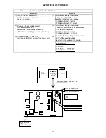
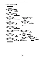
Item
Preparation
Procedure
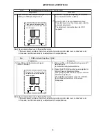
(1) Set signal generator output as
All White (Window ratio: 100%).
(1)
(2) Component signal (480i)
Video level : 0.700Vp-p
Sync level : 0.300Vp-p
Setup level : 0V
(2)
<Specification>
Video Colo
u
r temperature (Warm)
x=0.314 0.01
y=0.327 0.01
(3)
(4)
Check that Picture Menu is set as [RESET]
mode.
(3)
(4)
Video Colo
u
r Temperature Adjustment (Warm)
Perform the following adjustment with the remote
control.
Set the CRT Colo
u
r Analyzer (CA100) at the cent
re
of the panel.
Ensure that service adjustment
menu (submenu) No. 6, 7, 8 are all set as 255.
After receiving the video signal, step down
the two (or one) among adjustment No. 6, 7, 8 and
adjust the values as shown below.
(Note)
At least one of the data should be 255.
Set into Factory Adjustment mode.
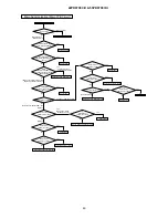
Item
Preparation
Procedure
(1)
Set signal generator output as All White
(Window ratio: 100%).
(1)
(2)
Component signal (480i)
Video level : 0.700Vp-p
Sync level : 0.300Vp-p
Setup level : 0V
(2)
(3)
(4)
Check that Picture Menu is set as
[RESET] mode.
(3)
(4)
Video Colo
u
r Temperature Adjustment (B&W)
Perform the following adjustment with
the remote control.
Set the CRT Colo
u
r Analyzer (CA-100) at
the cent
re
of the panel.
Ensure that service adjustment
menu (sub menu) No. 9, 10, 11 are all set as 255.
After receiving the video signal, step down
the two (or one) among adjustment No. 9,
10, 11 and adjust the values as shown
below.
(Note)
At least one of the data should be 255.
<Specification>
Video Colo
u
r temperature (B&W)
x=0.335 0.01
y=0.343 0.01
Set into Factory Adjustment mode.
Summary of Contents for 42PD9700C
Page 58: ...SM 011 POWER BOARD CIRCUIT SHEET 1 ...
Page 59: ...SM 011 POWER BOARD CIRCUIT SHEET 2 ...
Page 60: ...SM 011 POWER BOARD CIRCUIT SHEET 3 ...
Page 61: ...SM 011 POWER BOARD CIRCUIT SHEET 4 ...
Page 62: ...SM 011 POWER BOARD CIRCUIT SHEET 5 ...
Page 63: ...SM 011 MAIN BOARD CIRCUIT SHEET 1 ...
Page 64: ...SM 011 MAIN BOARD CIRCUIT SHEET 2 A WAKE UP MAIN 5 ...
Page 65: ...SM 011 MAIN BOARD CIRCUIT SHEET 3 ...
Page 66: ...SM 011 MAIN BOARD CIRCUIT SHEET 4 ...
Page 67: ...SM 011 MAIN BOARD CIRCUIT SHEET 5 MAIN 2 ...
Page 69: ...SM 011 SUB POWER BOARD CIRCUIT ...
Page 70: ...SM 011 CONTROL BOARD CIRCUIT ...
Page 71: ...SM 011 SOUND BOARD CIRCUIT ...
Page 74: ...SM 011 FC BOARD CIRCUIT SHEET 3 ...
Page 75: ...SM 011 FC BOARD CIRCUIT SHEET 4 about 7mA It is 0 4V at 22V to in press it ...
Page 76: ...SM 011 FC BOARD CIRCUIT SHEET 5 Female BM VIDEO change To IC202ARGB AMP ...
Page 78: ...SM 011 FC BOARD CIRCUIT SHEET 7 A B work C D work A B work C D work ...
Page 79: ...SM 011 FC BOARD CIRCUIT SHEET 8 ...
Page 80: ...SM 011 FC BOARD CIRCUIT SHEET 9 MAIN µ com ...
Page 81: ...SM 011 POWER BOARD ...
Page 82: ...SM 011 MAIN BOARD COMPONENT TOP SIDE ...
Page 83: ...SM 011 MAIN BOARD SOLDER BOTTOM SIDE ...
Page 85: ...SM 011 FC BOARD SOLDER BOTTOM SIDE COMPONENT TOP SIDE ...
Page 90: ...SM 011 WIRING ASSEMBLY DIAGRAM 1 ...
Page 91: ...SM 011 WIRING ASSEMBLY DIAGRAM 2 ...
Page 92: ...SM 011 WIRING ASSEMBLY DIAGRAM 3 ...
Page 93: ...SM 011 ASSEMBLY DIAGRAM ...
Page 95: ...THE UPDATED PARTS LIST FOR THIS MODEL IS AVAILABLE ON ESTA ...


