


3
42PD9700C/U & 55PD9700C/U
Digital Terrestrial Television Broadcasting
Converting into digital signal enables to provide more channels and various useful features, such as Electric
Programme Guide, Digital Teletext, and so on. Further, digital signal can create high quality picture.
Difference of broadcast signal method, divided into 42
/55
PD9700U and 42
/55
PD9700C according to country.
This logo indicates that the product is compliant with European Digital Broadcasting.
DVB is a registered trademark of the DVB Project.
This logo indicates that the product is set up to view digital terrestrial TV.
FREEVIEW and the FREEVIEW logo are trade marks of DVT Services Ltd and are used under license.
FREEVIEW Logo © DTV Services Ltd 2002.
This logo indicates that the product will work after implementation of full digital switchover.
The Digital logo is a Certification Mark.
Summary of Contents for 42PD9700C
Page 58: ...SM 011 POWER BOARD CIRCUIT SHEET 1 ...
Page 59: ...SM 011 POWER BOARD CIRCUIT SHEET 2 ...
Page 60: ...SM 011 POWER BOARD CIRCUIT SHEET 3 ...
Page 61: ...SM 011 POWER BOARD CIRCUIT SHEET 4 ...
Page 62: ...SM 011 POWER BOARD CIRCUIT SHEET 5 ...
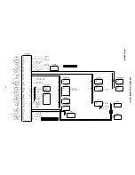
Page 63: ...SM 011 MAIN BOARD CIRCUIT SHEET 1 ...
Page 64: ...SM 011 MAIN BOARD CIRCUIT SHEET 2 A WAKE UP MAIN 5 ...
Page 65: ...SM 011 MAIN BOARD CIRCUIT SHEET 3 ...
Page 66: ...SM 011 MAIN BOARD CIRCUIT SHEET 4 ...
Page 67: ...SM 011 MAIN BOARD CIRCUIT SHEET 5 MAIN 2 ...
Page 69: ...SM 011 SUB POWER BOARD CIRCUIT ...
Page 70: ...SM 011 CONTROL BOARD CIRCUIT ...
Page 71: ...SM 011 SOUND BOARD CIRCUIT ...
Page 74: ...SM 011 FC BOARD CIRCUIT SHEET 3 ...
Page 75: ...SM 011 FC BOARD CIRCUIT SHEET 4 about 7mA It is 0 4V at 22V to in press it ...
Page 76: ...SM 011 FC BOARD CIRCUIT SHEET 5 Female BM VIDEO change To IC202ARGB AMP ...
Page 78: ...SM 011 FC BOARD CIRCUIT SHEET 7 A B work C D work A B work C D work ...
Page 79: ...SM 011 FC BOARD CIRCUIT SHEET 8 ...
Page 80: ...SM 011 FC BOARD CIRCUIT SHEET 9 MAIN µ com ...
Page 81: ...SM 011 POWER BOARD ...
Page 82: ...SM 011 MAIN BOARD COMPONENT TOP SIDE ...
Page 83: ...SM 011 MAIN BOARD SOLDER BOTTOM SIDE ...
Page 85: ...SM 011 FC BOARD SOLDER BOTTOM SIDE COMPONENT TOP SIDE ...
Page 90: ...SM 011 WIRING ASSEMBLY DIAGRAM 1 ...
Page 91: ...SM 011 WIRING ASSEMBLY DIAGRAM 2 ...
Page 92: ...SM 011 WIRING ASSEMBLY DIAGRAM 3 ...
Page 93: ...SM 011 ASSEMBLY DIAGRAM ...
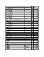
Page 95: ...THE UPDATED PARTS LIST FOR THIS MODEL IS AVAILABLE ON ESTA ...


