26
42PD9700C/U & 55PD9700C/U
Adj.
No
Function
Max.
value
Init.
Value
Device
ADJ. Items
Mode
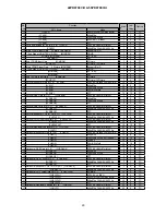
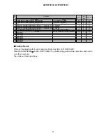
838
C3TBL_SEL_G
0
PDP
839
C3OTLEV_SEL_B
3
0
PDP
840
C3OTLEV_SEL_G
3
0
PDP
84
C3OTLEV_SEL_R
3
0
PDP
842
Reserved for EURO
-
-
-
843
Reserved for EURO
-
-
-
844
Reserved for EURO
-
-
-
845
Reserved for EURO
-
-
-
846
Reserved for EURO
-
-
-
847
Reserved for EURO
-
-
-
848
Reserved for EURO
-
-
-
849
Reserved for EURO
-
-
-
850
Reserved for EURO
-
-
-
85
Reserved for EURO
-
-
-
852
Reserved for EURO
-
-
-
853
Reserved for EURO
-
-
-
854
Reserved for EURO
-
-
-
855
Reserved for EURO
-
-
-
856
Reserved for EURO
-
-
-
857
Reserved for EURO
-
-
-
858
Reserved for EURO
-
-
-
859
Reserved for EURO
-
-
-
860
Reserved for EURO
-
-
-
86
Reserved for EURO
-
-
-
862
Reserved for EURO
-
-
-
863
Reserved for EURO
-
-
-
864
Reserved for EURO
-
-
-
865
Reserved for EURO
-
-
-
866
Reserved for EURO
-
-
-
867
Reserved for EURO
-
-
-
868
Reserved for EURO
-
-
-
869
Reserved for EURO
-
-
-
870
Reserved for EURO
-
-
-
87
Reserved for EURO
-
-
-
872
Reserved for EURO
-
-
-
873
Reserved for EURO
-
-
-
874
Reserved for EURO
-
-
-
875
Reserved for EURO
-
-
-
876
Reserved for EURO
-
-
-
877
Reserved for EURO
-
-
-
878
Reserved for EURO
-
-
-
879
Reserved for EURO
-
-
-
880
Reserved for EURO
-
-
-
88
Reserved for EURO
-
-
-
882
Reserved for EURO
-
-
-
883
Reserved for EURO
-
-
-
884
Reserved for EURO
-
-
-
885
Reserved for EURO
-
-
-
886
T/Text Sleep mode Enable
1:Enable
-
887
T/Text decoder SCL Time-out check
0:Normal, 1:Over 10ms
-
-
SDA6000
888
RS232C Terminal control mode 0:Terminal Mode, 1:DTT software
update
0
M30627
889
SiI9021 Read Data H-RES(H) Decimal mark ×100
-
-
HDMI
890
SiI9021 Read Data H-RES(L) Decimal mark ×1
-
-
HDMI
89
SiI9021 Read Data V-RES(H) Decimal mark ×100
-
-
HDMI
892
SiI9021 Read Data V-RES(L) Decimal mark ×1
-
-
HDMI
893
Reset function of accumulation time for WVGA/LCD Panel
0:Normal 1:Reset
0
M30627
894
Accumulation time for Panel (hours)
65535
-
PDP
895
Display of Panel map version
255
-
PDP
896
W/B Initialize
-
M30627
897
Gain adjustment of RGB amplifier (FLAON)
Main
-
-
FC
898
EEPROM Initialize(0:No, 1:Yes)
0
M30627
899
Enter to SUB adjust menu
-
-
M30627
900
Enter to service menu of FC sub mi-con
-
-
FC
Summary of Contents for 42PD9700C
Page 58: ...SM 011 POWER BOARD CIRCUIT SHEET 1 ...
Page 59: ...SM 011 POWER BOARD CIRCUIT SHEET 2 ...
Page 60: ...SM 011 POWER BOARD CIRCUIT SHEET 3 ...
Page 61: ...SM 011 POWER BOARD CIRCUIT SHEET 4 ...
Page 62: ...SM 011 POWER BOARD CIRCUIT SHEET 5 ...
Page 63: ...SM 011 MAIN BOARD CIRCUIT SHEET 1 ...
Page 64: ...SM 011 MAIN BOARD CIRCUIT SHEET 2 A WAKE UP MAIN 5 ...
Page 65: ...SM 011 MAIN BOARD CIRCUIT SHEET 3 ...
Page 66: ...SM 011 MAIN BOARD CIRCUIT SHEET 4 ...
Page 67: ...SM 011 MAIN BOARD CIRCUIT SHEET 5 MAIN 2 ...
Page 69: ...SM 011 SUB POWER BOARD CIRCUIT ...
Page 70: ...SM 011 CONTROL BOARD CIRCUIT ...
Page 71: ...SM 011 SOUND BOARD CIRCUIT ...
Page 74: ...SM 011 FC BOARD CIRCUIT SHEET 3 ...
Page 75: ...SM 011 FC BOARD CIRCUIT SHEET 4 about 7mA It is 0 4V at 22V to in press it ...
Page 76: ...SM 011 FC BOARD CIRCUIT SHEET 5 Female BM VIDEO change To IC202ARGB AMP ...
Page 78: ...SM 011 FC BOARD CIRCUIT SHEET 7 A B work C D work A B work C D work ...
Page 79: ...SM 011 FC BOARD CIRCUIT SHEET 8 ...
Page 80: ...SM 011 FC BOARD CIRCUIT SHEET 9 MAIN µ com ...
Page 81: ...SM 011 POWER BOARD ...
Page 82: ...SM 011 MAIN BOARD COMPONENT TOP SIDE ...
Page 83: ...SM 011 MAIN BOARD SOLDER BOTTOM SIDE ...
Page 85: ...SM 011 FC BOARD SOLDER BOTTOM SIDE COMPONENT TOP SIDE ...
Page 90: ...SM 011 WIRING ASSEMBLY DIAGRAM 1 ...
Page 91: ...SM 011 WIRING ASSEMBLY DIAGRAM 2 ...
Page 92: ...SM 011 WIRING ASSEMBLY DIAGRAM 3 ...
Page 93: ...SM 011 ASSEMBLY DIAGRAM ...
Page 95: ...THE UPDATED PARTS LIST FOR THIS MODEL IS AVAILABLE ON ESTA ...


