


54
42PD9700C/U & 55PD9700C/U
Code
stored up in
failure history
Self checking
item
Problem
Phenomenon
Cause
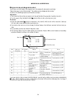
C10
No sync. (Snow noise)
OSD of “ ! Check Antenna ”
appears.
No connection of ANT cable
Preset tuning is not yet
H11
Tuner problem
Cannot receive the main
signal from antenna
Communication error of U101
H15
Composite video SW IC
problem
Cannot receive picture and
audio
Cannot change input mode
Communication error of I201
H16
Component video SW IC
problem
No component picture
Cannot change input mode
Communication error of I601
H31
Color demodulator IC
problem (sub)
Abnormal colo
u
r
Dark picture
Communication error of I504
H32
problem
Communication error of I501
H71
problem
Abnormal colo
u
r
Dark picture / No picture
No picture
Communication error of I400
F63
I
2
C-bus latch problem
Cannot store setting data
(Ex. Channel, Volume etc.)
SCL3/SDA3 latched up
Latest error code
Self Check
H11: OK H15: OK
H16: OK H31: OK
H32: OK H : OK
F63 F63 - - - - - - - - -
Self check result area
Failure history area
Check result
Check item
[OSD]
71
3D separator ZC
HDMI IC
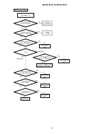
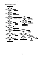
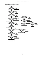
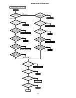
Signal circuit self-diagnosis function
This function is for the failure of the signal circuit, for example the phenomenon as below:
"Sometimes power turns off abnormally." "Sometimes picture disappears abnormally."
To enter to this Self-Diagnosis mode, follow the next steps:
Preparation:
1) The Power Cord should be connected to AC line and the Main Power switch should be turned on.
2) Turn the power off by the SUB-POWER( ) button of the monitor or the remote control.
Procedure:
1) Press the SUB-POWER( ) button and button on the bottom of the monitor at the same time, and keep
it for more than 5 seconds after the power turned on.
2) The monitor will be turned on, and it will display On-Screen Display of the Self-check result and the failure history as
below.
3) Any operation would cancel the Self -Diagnosis mode.
4) The following table shows the OSD symbols and contents of failure PWB in which failure most probably
would be allocated according to the number of blinks.
If you clear history of failure, make FACTORY RESET: enter the factory setting mode; press the SUB-POWER(
) button, INPUT SELECT( ) button and button on the bottom of the monitor at the same time. And keep it
for more than 5 seconds after the power turned on.
Summary of Contents for 42PD9700C
Page 58: ...SM 011 POWER BOARD CIRCUIT SHEET 1 ...
Page 59: ...SM 011 POWER BOARD CIRCUIT SHEET 2 ...
Page 60: ...SM 011 POWER BOARD CIRCUIT SHEET 3 ...
Page 61: ...SM 011 POWER BOARD CIRCUIT SHEET 4 ...
Page 62: ...SM 011 POWER BOARD CIRCUIT SHEET 5 ...
Page 63: ...SM 011 MAIN BOARD CIRCUIT SHEET 1 ...
Page 64: ...SM 011 MAIN BOARD CIRCUIT SHEET 2 A WAKE UP MAIN 5 ...
Page 65: ...SM 011 MAIN BOARD CIRCUIT SHEET 3 ...
Page 66: ...SM 011 MAIN BOARD CIRCUIT SHEET 4 ...
Page 67: ...SM 011 MAIN BOARD CIRCUIT SHEET 5 MAIN 2 ...
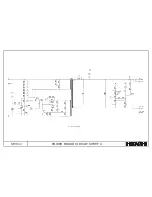
Page 69: ...SM 011 SUB POWER BOARD CIRCUIT ...
Page 70: ...SM 011 CONTROL BOARD CIRCUIT ...
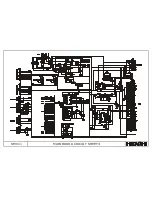
Page 71: ...SM 011 SOUND BOARD CIRCUIT ...
Page 74: ...SM 011 FC BOARD CIRCUIT SHEET 3 ...
Page 75: ...SM 011 FC BOARD CIRCUIT SHEET 4 about 7mA It is 0 4V at 22V to in press it ...
Page 76: ...SM 011 FC BOARD CIRCUIT SHEET 5 Female BM VIDEO change To IC202ARGB AMP ...
Page 78: ...SM 011 FC BOARD CIRCUIT SHEET 7 A B work C D work A B work C D work ...
Page 79: ...SM 011 FC BOARD CIRCUIT SHEET 8 ...
Page 80: ...SM 011 FC BOARD CIRCUIT SHEET 9 MAIN µ com ...
Page 81: ...SM 011 POWER BOARD ...
Page 82: ...SM 011 MAIN BOARD COMPONENT TOP SIDE ...
Page 83: ...SM 011 MAIN BOARD SOLDER BOTTOM SIDE ...
Page 85: ...SM 011 FC BOARD SOLDER BOTTOM SIDE COMPONENT TOP SIDE ...
Page 90: ...SM 011 WIRING ASSEMBLY DIAGRAM 1 ...
Page 91: ...SM 011 WIRING ASSEMBLY DIAGRAM 2 ...
Page 92: ...SM 011 WIRING ASSEMBLY DIAGRAM 3 ...
Page 93: ...SM 011 ASSEMBLY DIAGRAM ...
Page 95: ...THE UPDATED PARTS LIST FOR THIS MODEL IS AVAILABLE ON ESTA ...


