2
42PD9700C/U & 55PD9700C/U
PRECAUTIONS
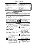
How to clean the plasma screen panel of the monitor
Before cleaning the monitor, turn off the monitor and disconnect the power plug from the power outlet.
To prevent scratching or damaging the plasma screen face, do not knock or rub the surface with sharp or
hard objects. Clean the screen with a soft cloth moistened with warm water and dry with a soft cloth. If it is
not enough, then use a cloth with mild detergent. Do not use harsh or abrasive cleaners.
How to clean the cabinet of the monitor
Use a soft cloth to clean the cabinet and control panel of the monitor. When excessively soiled dilute a neu
-
tral detergent in water, wet and wring out the soft cloth and afterward wipe with a dry soft cloth.
Never use acid/alkaline detergent, alcoholic detergent, abrasive cleaner, powder soap, OA cleaner, car wax,
glass cleaner, etc. especially because they would cause discoloration, scratches or cracks.
Information for users applicable in European Union countries
This symbol on the product or on its packaging means that your electrical and electronic
equipment should be disposed at the end of life separately from your household wastes.
There are separate collection systems for recycling in EU. For more information, please con
-
tact the local authority or the dealer where you purchased the product.
1. Features
Large-screen, high-definition plasma display panel
The 42-inch colo
u
r plasma display panel, with a resolution of 1024 (H) x 1080 (V) pixels, creates a high-definition,
large-screen(aspect ratio : 16:9) and low-profile flat display. Free from electromagnetic interferences from geo
-
magnetic sources and ambient power lines, the panel produces high-quality display images free from color mis
-
convergence and display distortion.
High Performance Digital Processor
A wide range of input signals can be handed,including composite, component,and HDMI.High Definition Digital
Processor creates the fine-textured image with dynamic contrast. In addition, it corresponds to a broad array of
personal computer signals, from 640 x 400 and 640 x 480 VGA to 1600 x 1200 UXGA.(Analog Input)
Easy-to-use remote control and on screen display system
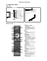
The remote control included eases the work of setting display controls. Further, the on-screen display sys
-
tem, displays the status of signal reception and display control settings in an easy-to-view fashion.
Connecting to an Audio Visual Device
• Three Scart terminals
*
, composite/S terminal
*2
, a component terminal
*3
, and two HDMI terminals have been
added. A composite video output terminal is also provided as a monitoring output.
*
AV1 scart applies to composite/ S-video
AV2 and 3 scart applies to composite/ RGB
*2
AV5 composite/S-Video=Side Input
*3
AV4 can be connected to the equipment with either component or composite Output.
• A wide range of devices can be also connected besides personal computers.
SD card slot installed
Power Swivel Feature
It allows turning the plasma display left or right within ±30 degree using the remote control.
Summary of Contents for 42PD9700C
Page 58: ...SM 011 POWER BOARD CIRCUIT SHEET 1 ...
Page 59: ...SM 011 POWER BOARD CIRCUIT SHEET 2 ...
Page 60: ...SM 011 POWER BOARD CIRCUIT SHEET 3 ...
Page 61: ...SM 011 POWER BOARD CIRCUIT SHEET 4 ...
Page 62: ...SM 011 POWER BOARD CIRCUIT SHEET 5 ...
Page 63: ...SM 011 MAIN BOARD CIRCUIT SHEET 1 ...
Page 64: ...SM 011 MAIN BOARD CIRCUIT SHEET 2 A WAKE UP MAIN 5 ...
Page 65: ...SM 011 MAIN BOARD CIRCUIT SHEET 3 ...
Page 66: ...SM 011 MAIN BOARD CIRCUIT SHEET 4 ...
Page 67: ...SM 011 MAIN BOARD CIRCUIT SHEET 5 MAIN 2 ...
Page 69: ...SM 011 SUB POWER BOARD CIRCUIT ...
Page 70: ...SM 011 CONTROL BOARD CIRCUIT ...
Page 71: ...SM 011 SOUND BOARD CIRCUIT ...
Page 74: ...SM 011 FC BOARD CIRCUIT SHEET 3 ...
Page 75: ...SM 011 FC BOARD CIRCUIT SHEET 4 about 7mA It is 0 4V at 22V to in press it ...
Page 76: ...SM 011 FC BOARD CIRCUIT SHEET 5 Female BM VIDEO change To IC202ARGB AMP ...
Page 78: ...SM 011 FC BOARD CIRCUIT SHEET 7 A B work C D work A B work C D work ...
Page 79: ...SM 011 FC BOARD CIRCUIT SHEET 8 ...
Page 80: ...SM 011 FC BOARD CIRCUIT SHEET 9 MAIN µ com ...
Page 81: ...SM 011 POWER BOARD ...
Page 82: ...SM 011 MAIN BOARD COMPONENT TOP SIDE ...
Page 83: ...SM 011 MAIN BOARD SOLDER BOTTOM SIDE ...
Page 85: ...SM 011 FC BOARD SOLDER BOTTOM SIDE COMPONENT TOP SIDE ...
Page 90: ...SM 011 WIRING ASSEMBLY DIAGRAM 1 ...
Page 91: ...SM 011 WIRING ASSEMBLY DIAGRAM 2 ...
Page 92: ...SM 011 WIRING ASSEMBLY DIAGRAM 3 ...
Page 93: ...SM 011 ASSEMBLY DIAGRAM ...
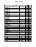
Page 95: ...THE UPDATED PARTS LIST FOR THIS MODEL IS AVAILABLE ON ESTA ...


