HIKVISION DS-C12L Series User Manual Download Page 24

Before You Start
• You have connected the loop cables and sync cables for the devices physically.

• You have added the devices to be cascaded to the client.
Steps

1. Click Device Topology to enter the device cascading topology configuration interface.

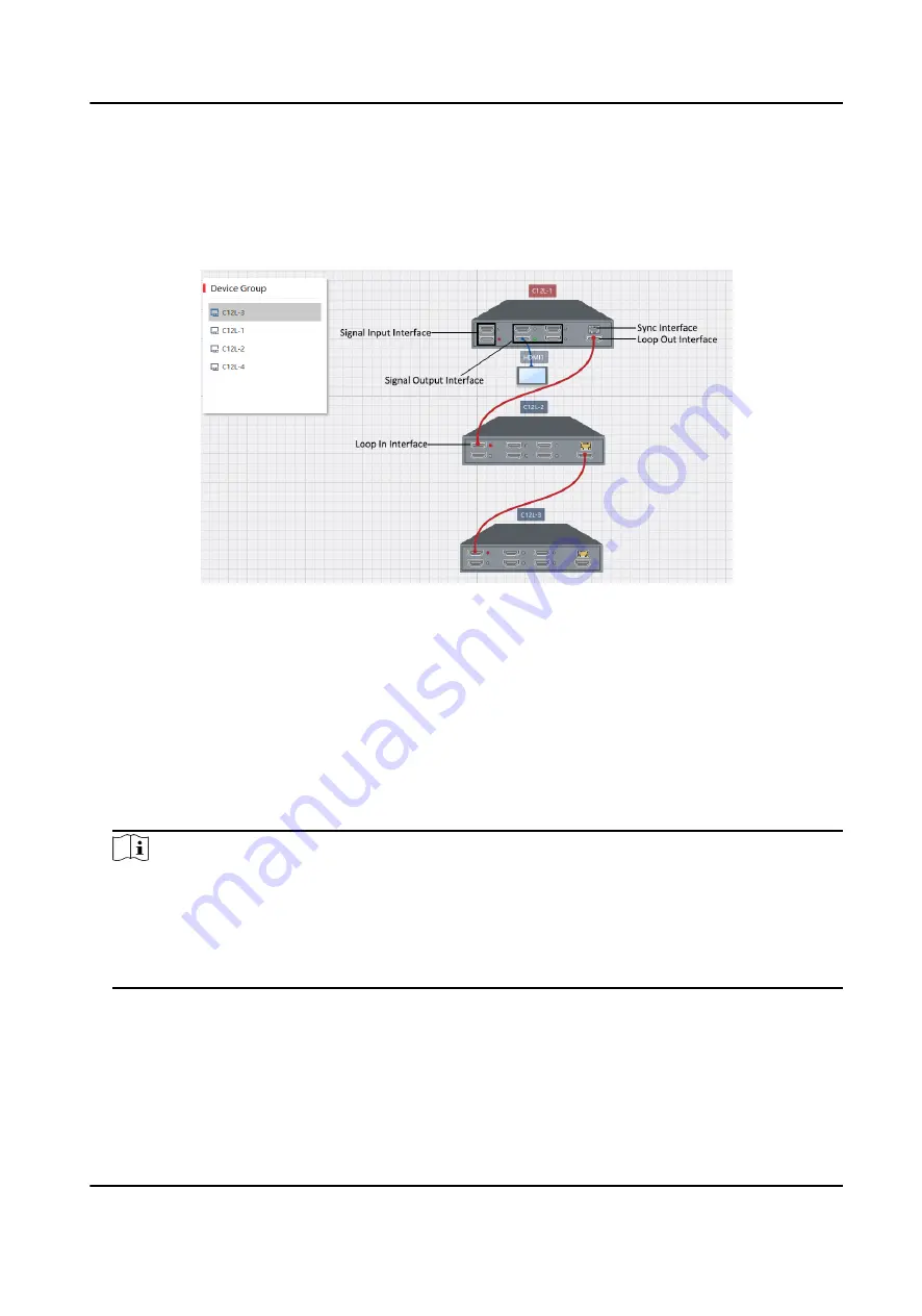
Figure 2-5 Configure Cascading Topology

2. In the device list on the left, drag the desired devices to the topology area on the middle. You

can drag to change the positions or press the mouse wheel to change the size of the topology

area.

3. Draw the loop lines according to the physical cable connections.

1) Move your mouse on the loop out interface of the master device, and left-click and hold your

mouse.

2) When the interface is circled in red and a red point appears in the middle, hold and move the

mouse to draw a connection line to the loop in interface of one of the slave devices.

3) Repeat the above steps to complete the rest of devices.

Note

• The cascading topology relationship must be consistent with the actual device relationship.

• You can view device information such as the IP address and serial number by double clicking

the device.

• If you want to change the cascading relationship, press the Delete key to delete the lines and

draw them again.

4. Click Save.
Result
After the cascading topology is configured, only the two HDMI input interfaces of the master

device can be used to input signals.

Video Wall Controller User Manual

15

Summary of Contents for DS-C12L Series

Page 1: ...Video Wall Controller User Manual...

Page 2: ...EVENT WILL HIKVISION BE LIABLE TO YOU FOR ANY SPECIAL CONSEQUENTIAL INCIDENTAL OR INDIRECT DAMAGES INCLUDING AMONG OTHERS DAMAGES FOR LOSS OF BUSINESS PROFITS BUSINESS INTERRUPTION OR LOSS OF DATA COR...

Page 3: ...TIVITIES IN THE CONTEXT RELATED TO ANY NUCLEAR EXPLOSIVE OR UNSAFE NUCLEAR FUEL CYCLE OR IN SUPPORT OF HUMAN RIGHTS ABUSES IN THE EVENT OF ANY CONFLICTS BETWEEN THIS MANUAL AND THE APPLICABLE LAW THE...

Page 4: ...cause harmful interference 2 This device must accept any interference received including interference that may cause undesired operation EU Conformity Statement This product and if applicable the supp...

Page 5: ...Caution Indicates a potentially hazardous situation which if not avoided could result in equipment damage data loss performance degradation or unexpected results Note Provides additional information t...

Page 6: ...attempt to disassemble the product yourself We shall not assume any responsibility for problems caused by unauthorized repair or maintenance Please enhance the protection for personal information and...

Page 7: ...3 Magnetic Mount 8 2 2 Connect Cables 9 2 2 1 Cable Connection Requirements 9 2 2 2 Cable Connection Description 10 2 3 Activate Your Device 12 2 3 1 Activate on Client 12 2 3 2 Activate on SADP 13 2...

Page 8: ...Off Audio on the Video Wall 24 3 2 5 Change the Name of a Signal Source 24 3 3 Configure a Background Picture 25 Chapter 4 Device Maintenance 26 4 1 Check Device Topology Status 26 4 2 Change Device P...

Page 9: ...6 5 Upgrade a Device Remotely 33 Video Wall Controller User Manual viii...

Page 10: ...video wall application scenarios such as shopping malls conference rooms and lecture halls 1 2 Key Feature Two HDMI inputs and signal switching by button customizable input resolution Four HDMI outpu...

Page 11: ...Description 1 CONSOLE Debugging serial interface built in with an RS232 to UART interface 2 IR IN Reserved 3 PWR Power indicator Turns steady red after power on 4 STAT System status indicator Unlit d...

Page 12: ...erface 1 4 2 Rear Panel Figure 1 3 Rear Panel Table 1 3 Rear Panel Interface Description No Name Description 1 HDMI IN 1 HDMI input interface 1 up to 4K 60 Hz input 2 HDMI IN 2 HDMI input interface 2...

Page 13: ...put interface for synchronizing signals between devices 11 Sync IN Sync input interface for synchronizing signals between devices 12 LAN 10 100 1000 Mbps adaptive network interface IEEE 802 3at PoE 13...

Page 14: ...Figure 1 4 Client Manamgment Software Video Wall Controller User Manual 5...

Page 15: ...d in later sections Figure 2 1 Installation and Configuration Process 2 1 Install Your Device Devices can be installed in three ways stacking wall mount and magnet mount Decide your installation way b...

Page 16: ...wiring and ventilation Steps 1 Take out the four rubber feet from the package and stick them onto the bottom of your device Repeat this step to complete the installation of rubber feet of the other d...

Page 17: ...evice and mount your device onto the screws Figure 2 3 Mounting Hole Position 3 Repeat the above steps to complete the installation of the rest of your devices 2 1 3 Magnetic Mount If you want to moun...

Page 18: ...luding the grounding cables network cables video and audio cables serial cables cascading cables sync cables and power cables 2 2 1 Cable Connection Requirements Different application scenarios requir...

Page 19: ...Cable Connection Description See the following table for details about how to connect cables Note All cables mentioned in the following table require you to purchase separately Table 2 2 Cable Connec...

Page 20: ...e of the slave device to the loop in interface of the next slave device with an HDMI cable The rest can be done in the same manner 5 Sync cable 1 Connect the sync out interface of the first device to...

Page 21: ...network segment with your device Steps 1 Run and log in to the client 2 Click Device Management Online devices on the same network segment are searched out and displayed in the lower area 3 In the de...

Page 22: ...ity system resetting the password monthly or weekly can better protect your product 4 Click Activate Device Status changes into Active 5 Optional Change the network parameters of the device in Modify...

Page 23: ...nfigure Network Parameters After your device is added to the client you can configure network parameters of your device as needed including the IP address subnet mask and gateway Steps 1 On the Device...

Page 24: ...of the master device and left click and hold your mouse 2 When the interface is circled in red and a red point appears in the middle hold and move the mouse to draw a connection line to the loop in i...

Page 25: ...omize the resolution of the input signal sources so that they are matched Steps 1 On the Device Management interface select the desired device in the list and click Remote Configuration 2 Click Video...

Page 26: ...lay Steps 1 On the Device Management interface select the desired device in the list and click Remote Configuration 2 Click Video Display OSD Display Figure 2 7 Configure OSD Display 3 Select Signal S...

Page 27: ...tem Serial Port Configuration Figure 2 8 Configure Serial Parameters 3 Configure serial parameters including Serial Port Type Baud Rate Data Bit Stop Bit Parity and Flow Control 4 Click Save Note Ensu...

Page 28: ...the video wall on the client 3 1 1 Add a Video Wall Add a virtual video wall on the client according to the physical video wall for control and management Steps 1 Click Video Wall to enter the video w...

Page 29: ...CD type set the output type to LCD If your video wall is a LED type set the output type to LED 3 If your video wall is an LCD type configure the resolution You are recommended to configure a resolutio...

Page 30: ...that your video wall has the same height in the same row and the same width in the same column 5 Optional Configure Background as needed 6 Optional Check Batch Configuration to copy the configuration...

Page 31: ...nk the decoding output of the master device Otherwise an error may occur 3 2 Display Signal Sources on the Video Wall After the video wall is created and configured you can display the signal sources...

Page 32: ...the video wall to open a decoding window automatically The window is a splicing window and spans over all the decoding outputs by default Steps 1 Click Video Wall to enter the video wall management in...

Page 33: ...tart to display the latter one Front panel Press the SWITCH button on the front panel of the device to switch between the two signal inputs RS 232 485 serial interface Connect with an external keyboar...

Page 34: ...to use the default background picture of the system but not import other pictures Steps 1 Click Video Wall to enter the video wall management interface Figure 3 7 Configure a Background Picture 2 Cli...

Page 35: ...ng relationship cable connection status and status of signal input and output interfaces Device names are displayed above device pictures The name in red indicates the corresponding device is the mast...

Page 36: ...ray 4 2 Change Device Password You can change the password used to log in to your device on the client Steps 1 On the Device Management interface select the desired device in the list and click Remote...

Page 37: ...ce password is cleared for you to set a new one 5 Enter a new password and confirm the password Caution We highly recommend you to create a strong password of your own choosing using a minimum of 8 ch...

Page 38: ...ent interface select the desired device in the list and click Remote Configuration 2 Click System Device Information to view device information such as the device type serial No or version No Video Wa...

Page 39: ...ystem General 3 Change the Device Name or Device No as needed 4 Click Save 5 2 Configure Device Time If your device time is incorrect set the time zone or manually synchronize time to correct the time...

Page 40: ...Secure Shell is a protocol to ensure security of remote login You can change the SSH configuration as needed Steps 1 On the Device Management interface select the desired device in the list and click...

Page 41: ...rong password of your own choosing using a minimum of 8 characters including at least three kinds of following categories upper case letters lower case letters numbers and special characters in order...

Page 42: ...ll will clear all parameters and restore the parameters to factory settings You are recommended to export the configuration file first before restoring parameters 6 4 Restart a Device Remotely You can...

Page 43: ...UD16589B...

Reviews: