HF-LPT220 Low Power WiFi Module User Manual
Shanghai High-Flying Electronics Technology Co., Ltd(www.hi-flying.com)
- 8 -
LIST OF FIGURES
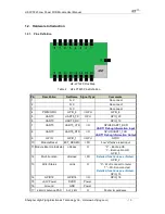
HF-LPT220 Pins Map........................................................................................................................ 13
Figure 1.
HF-LPT220 Mechanical Dimension .................................................................................. 15
Figure 2.
HF-LPT220 PCB Symbol Size ......................................................................................... 15
Figure 3.
Suggested Module Placement Region ............................................................................. 16
Figure 4.
HF-LPT220 Evaluation Kit ............................................................................................... 17
Figure 5.
HF-LPT220 Order InformationTypical Application............................................................. 18
Figure 6.
HF-LPT220 Hardware Typical Application ........................................................................ 18
Figure 7.
HF-LPT220 Basic Wireless Network Structure ................................................................. 20
Figure 8.
HF-LPT220 STA Network Structure ................................................................................. 20
Figure 9.
Socket B function demo ................................................................................................... 24
Figure 10.
Multi-TCP Link Data Transmition Structure ................................................................... 24
Figure 11.
STA Interface Debug Connection ................................................................................. 25
Figure 12.
AP Interface Debug Connection ................................................................................... 26
Figure 13.
“CommTools” Serial Debug Tools................................................................................. 26
Figure 14.
“TCPUDPDbg” Tools Create Connection ...................................................................... 26
Figure 15.
“TCPUDPDbg” Tools Setting ........................................................................................ 27
Figure 16.
“TCPUDPDbg” Tools Connection ................................................................................. 27
Figure 17.
Wireless Control Application ......................................................................................... 27
Figure 18.
Remote Management Application ................................................................................. 28
Figure 19.
Transparent Serial Port Application .............................................................................. 28
Figure 20.
HF-LPT220 Default UART Port Parameters.................................................................. 29
Figure 21.
Switch to Configuration Mode ....................................................................................... 29
Figure 22.
”AT+H” Instruction for Help ........................................................................................... 30
Figure 23.
Reflow Soldering Profile ............................................................................................... 56
Figure 24.
Shipping Information .................................................................................................... 57

