


Inspection 11
Rev. A
1219 US 35 West P.O. Box 60 Eaton, OH 45320 (937)456-8400 Fax (937)456-8402 www.hennypenny.com
Plumbing Inspection
Objective
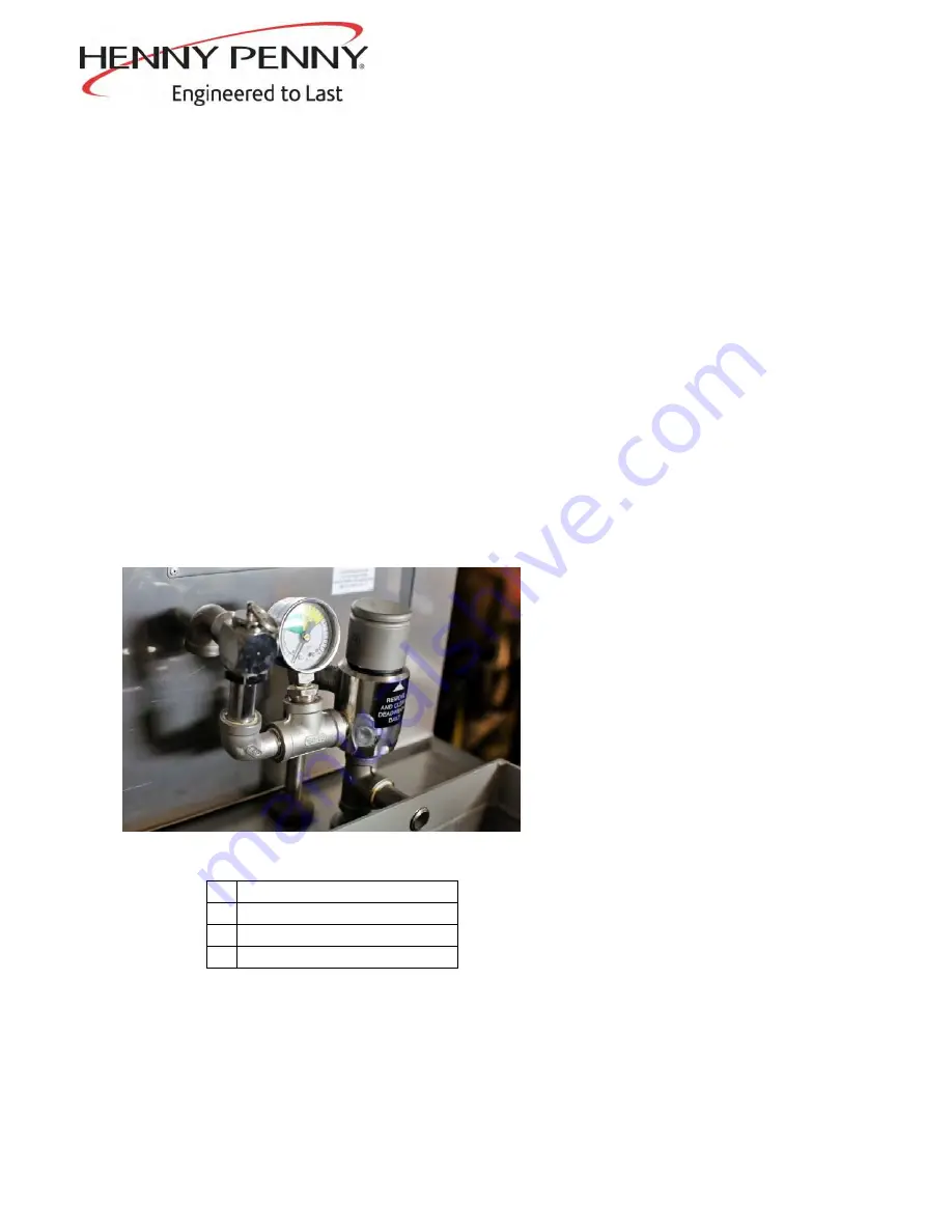
Inspect the plumbing from the deadweight to the condensation box and from the outlet in the
fry pot, through the pressure solenoid to the condensation box are free and clear from
obstruction (figures 1&2). Obstructions can be detected during the lid lock engagement /
disengagement procedure. During this test, if pressure exceeds 12 psi, this is a sign that the
deadweight would need to be cleaned and or deadweight plumbing is obstructed and would
need to be cleaned or replaced. If the pressure gauge does not read zero at the end of the test,
this is a sign that the pressure solenoid or related plumbing would need to be cleaned or if
damaged or obstructed bad enough, components would need to be replaced. If any
obstructions are detected, follow the procedure to remove obstruction below.
Why is this important? Keeping this plumbing free and clear from obstruction keeps product
quality high. If there are issues with deadweight plumbing, product issues will result. Set points
are designed around 12psi. If the pressure solenoid or related plumbing is obstructed, product
will overcook as the time for the pressure to reach zero increases the amount of time product is
in the fryer.
A Fry Pot Outlet
B
Plumbing to Solenoid Valve
C
Deadweight Valve
D Deadweight Plumbing
Plumbing Cleaning Procedure
1.
Remove rear cover of fryer.
For Deadweight Obstructions
(pressure too high)
2.
Clean the outlet of fry pot to
the deadweight valve with a
flexible wire brush (figure 1).
Figure 4.
Figure 1.
Plumbing as seen from the front of the fryer.
A
B
C
D
Summary of Contents for PFG-691
Page 1: ...Henny Penny Pressure Fryer Model PFG 691 TECHNICAL MANUAL...
Page 2: ......
Page 52: ...Model 691 2 34 SN FH001JC ABOVE Aug 2004...
Page 53: ...Model 691 2 35 SN FH001JC ABOVE Aug 2004...
Page 54: ...Model 691 2 36 SN FH001JC ABOVE Aug 2004...
Page 55: ...Model 691 2 37 BELOW SN FH001JC March 2004...
Page 56: ...Model 691 2 38 BELOW SN FH001JC March 2004...
Page 57: ...Model 691 2 39 BELOW SN FH001JC March 2004...
Page 58: ...Model 691 2 40 BELOW SN FH001JC March 2004...
Page 60: ......
Page 62: ...Model 691 3 2 FIGURE 3 1 FRAME COVER ASSEMBLY Oct 2004...
Page 68: ...Model 691 3 8 FIGURE 3 6 LID COVER ASSEMBLY March 2007...
Page 70: ...Model 691 3 10 FIGURE 3 7 DRAIN PAN FILTER ASSEMBLY Aug 2010...
Page 72: ...Model 691 3 12 FIGURE 3 8A FILTER PUMP ASSEMBLY SN LH028JC BELOW Aug 2010...
Page 74: ...Model 691 3 14 FIGURE 3 8B FILTER PUMP ASSEMBLY SN LH029JC ABOVE Oct 2004...
Page 77: ...Model 691 3 17 FIGURE 3 10 GAS BURNER ASSEMBLY May 2005...
Page 79: ...Model 691 3 19 FIGURE 3 11 GAS PIPING CONTROLS Dec 2009...
Page 84: ...Model 691 3 24 FIGURE 3 15 DEADWEIGHT SOLENOID ASSY SN AP0802029 ABOVE Aug 2010...
Page 87: ...Model 691 3 27 FIGURE 3 16B STEAM BOX HOSE ASSEMBLY SN AP0802028 BELOW Aug 2010...
Page 89: ...Model 691 3 29 FIGURE 3 17 FLUE ASSEMBLY BLOWER SN AP0802028 BELOW Dec 2009...
Page 93: ...Model 691 3 33 FIGURE 3 18 SOLENOID VALVE ASSEMBLY Sept 2005...
Page 95: ...Model 691 3 35 FIGURE 3 19 FRYPOT DRAIN PIPING Oct 2008...
Page 97: ...Model 691 3 37 FIGURE 3 20 LIFT BEAM SHROUDS SN AP0802028 BELOW Aug 2010...
Page 99: ...Model 691 3 39 FIGURE 3 21 COUNTERWEIGHT PULLEY SYSTEM SN AP0802028 BELOW Aug 2010...
Page 139: ...Inspection 12 Rev A...
Page 140: ...Inspection 12 Rev A...
Page 141: ...Inspection 12 Rev A...
Page 144: ...Inspection 15 Rev A...
Page 145: ...Inspection 16 Rev A...
Page 146: ...Inspection 16 Rev A...
Page 159: ...Inspection 24 Rev A Figure 2 1...
Page 160: ...Inspection 24 Rev A Figure 2 2...
Page 183: ......


