


Heinzinger electronic GmbH
Phone: +49 (0) 8031 2458 0
www.heinzinger.com
Anton-Jakob-Str. 4, 83026 Rosenheim
Fax: + 49 (0) 8031 2458 58
Germany
Page 33
ERS COMPACT
1.9.7.2
USB port
The front USB port is easier to access than the one on the rear side and intended for quick setup of DC terminal
related values and settings. Doing so is only necessary and possible in these two situations:
1. The Slave module shall run as stand-alone device which isn’t controlled by a master.
2.
The Slave module shall, due to the lack of a suitable standard model, be the master of other Slave modules.
Both situations are only secondary, as the primary and normal function of a Slave module is to be a slave in a
master-slave system where it’s assigned all required settings and values from the master.
When running any of the above listed situations following applies for the USB port remote control:
•
Reduced instruction set for master-slave configuration, set values (U, I, P, R) and protections
(OVP, OCP, OPP). For details about the instruction set see
“3.6.3.4. The front USB port of
Slave models”.
•
Taking over remote control in order to change the configuration is only possible while the unit
isn’t online with the master, which either requires to temporarily deactivate master-slave on
the master or to switch the master off
1.9.7.3
Pushbutton “On / Off”
This button can be used to switch the DC terminal on or off during manual control, i.e. the device isn’t
in remote control by a master or via any of the USB ports (LED “Remote” = off). Once pushed to switch
the DC terminal on, the device would regulate it to the last values it has stored. Since all the DC terminal
related values aren’t displayed, operating that button has to be done with caution.
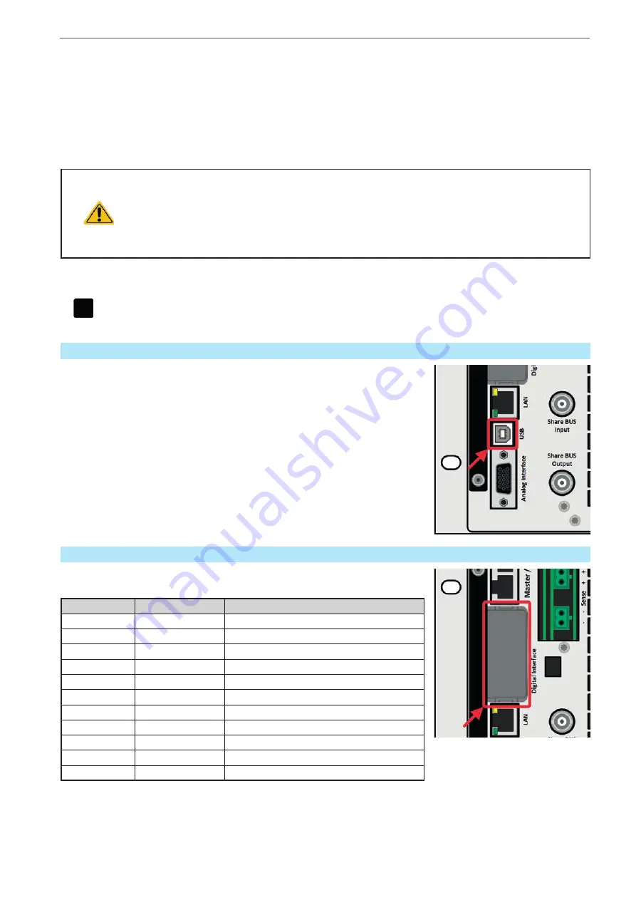
1.9.8
USB port (rear side)
The USB port on the rear side of the device is provided for communication with
the device and for firmware updates. The included USB cable can be used to
connect the device to a PC (USB 2.0 or 3.0). The driver is delivered with the
device and installs a virtual COM port. Details about remote control can be
found in form of a programming guide on the included USB stick or on the web
site of the manufacturer.
The device can be addressed via this port either using the international stan-
dard ModBus RTU protocol or by SCPI language. The device recognizes the
message protocol used automatically.
If remote control is in operation the USB port has no priority over either the
interface module (see below) or the analog interface and can, therefore, only
be used alternatively to these. However, monitoring is always available.
1.9.9
Interface module slot (standard models)
This slot on the rear side of the device is can receive various modules of the
IF-AB interface series. The following options are available:
Name
Description
IF-AB-CANO
CANopen, 1x DB9, male
IF-AB-RS232
RS 232, 1x DB9, male (null modem)
IF-AB-PBUS
Profibus DP-V1 Slave, 1x DB9, female
IF-AB-ETH1P
Ethernet, 1x RJ45
IF-AB-PNET1P
ProfiNET IO, 1x RJ45
IF-AB-MBUS1P
ModBus TCP, 1x RJ45
IF-AB-ETH2P
Ethernet, 2x RJ45
IF-AB-MBUS2P
ModBus TCP, 2x RJ45
IF-AB-PNET2P
ProfiNET IO, 2x RJ45
IF-AB-CAN
CAN 2.0 A / 2.0 B, 1x DB9, male
IF-AB-ECT
EtherCAT, 1x RJ45
The modules can be installed by the user and hence retrofitted without problem. A firmware update of the device
may be necessary in order to recognize and support certain modules.