Heat & Glo • MEZZO36-C/ST-C, MEZZO48-C/ST-C, MEZZO60-C/ST-C, MEZZO72-C/ST-C Installation Manual • 2600-980 Rev. D • 9/19
66
C. Mantel and Wall Projections
WARNING! Risk of Fire!
Comply with all minimum clear-
ances to combustibles as specified. Framing closer than the
minimums listed must be constructed entirely of noncom-
bustible materials (i.e., steel studs, concrete board, etc.)
Combustible Mantels
Note: For non-combustible fireplace finish material (marble,
stone, etc) specifications refer to Section 10.A.
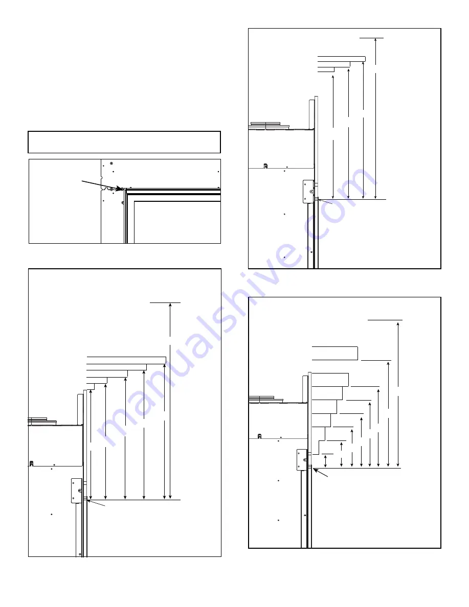
Figure 10.12 Minimum Vertical and Maximum Horizontal
Dimensions of Combustibles - MEZZO36-C,
MEZZO36ST-C, MEZZO48-C and MEZZO48ST-C
MEASUREMENT FROM
TOP EDGE OPENING
18
20
23
26
29
31
TO CEILING
9
12
6
3
1
Measurement from top edge opening
to bottom of appliance = 24-1/2 IN.
MAX.
Note:
All measurements in inches.
Figure 10.13 Minimum Vertical and Maximum Horizontal
Dimensions of Combustibles - MEZZO60-C,
MEZZO60ST-C, MEZZO72-C and MEZZO72ST-C
Note:
All measurements in inches.
TOP OF APPLIANCE OPENING
Figure 10.11 Location of Appliance Opening
MEASUREMENT FROM
TOP EDGE OPENING
24
27
30
31
TO CEILING
9
6
3
Measurement from top edge opening
to bottom of appliance = 24-1/2 IN.
MAX.
Figure 10.14 Minimum Vertical and Maximum Horizontal
Dimensions of Combustibles - Passive Heat Kit
Installed (All Sizes)
MEASUREMENTS FROM TOP EDGE
OF THE APPLIANCE OPENING
4
5
6
13-16
3
2
1
6
7
8
9
10
11
18
31
MAX.
MIN.
TO CEILING
Measurement from top edge of opening
to bottom of appliance = 24-1/2 IN.
Note:
All measurements in inches.
If the Passive Heat kit will be installed, see Figure 10.19
for details regarding clearances to combustibles in addi
-
tion to the requirements for Combustible and Non-Com
-
bustible Mantel diagrams and the Mantel Leg/Wall Pro
-
jection diagrams (Figure 10.11-Figure 10.18).


