70
2420344510 E
11.11
AUS
Telescopic handlers
D
- Operation
2.5 -
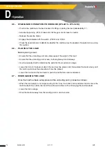
STABILISER OPERATION PROCEDURE (HTL4010 - HTL3210)
• Position the machine in the best location for lifting or placing the load (Gradeability 3 °).
• Actuate the parking (P214) brake and shift the gear control lever to neutral.
• Release the service brake.
• Engage the stabilizers with the switch ( P208 ) and P209.
• Check the level indicator to determine whether the machine must be levelled, if required, do so using
the joystick.
2.6 -
PLACING THE LOAD
Before placing a load :
• Ensure that the unloading point can safely support the weight of the load.
• Ensure that the unloading point is level, both lengthways and sideways.
• Use the capacity chart to determine the permitted boom extension range.
• Lower the forks to the level at which the load must be placed, and then extend the boom slowly until
the load is just above the area where it must be placed.
• Lower the boom until the load rests in position and the forks can be retracted.
2.7 -
DISENGAGING THE LOAD
Once the load has been safely placed at the unloading point, proceed as follows :
• When the load weight is no longer resting on the forks, the boom can be retracted and/or move the
machine back from under the load if the surface so allows without changing the machine level.
• Lower the fork carriage.
• Drive the machine away from the landing point to continue work.
Summary of Contents for HTL 3210
Page 2: ...2 2420344510 E 11 11 AUS Telescopic handlers...
Page 12: ...12 2420344510 E 11 11 AUS Telescopic handlers...
Page 74: ...74 2420344510 E 11 11 AUS Telescopic handlers D Operation...
Page 80: ...80 2420344510 E 11 11 AUS Telescopic handlers E Attachments HTL4010 load capacity chart...
Page 146: ...146 2420344510 E 11 11 AUS Telescopic handlers F Emergency procedure...
Page 159: ...159 2420344510 E 11 11 AUS Telescopic handlers H Lubrication and maintenance...

