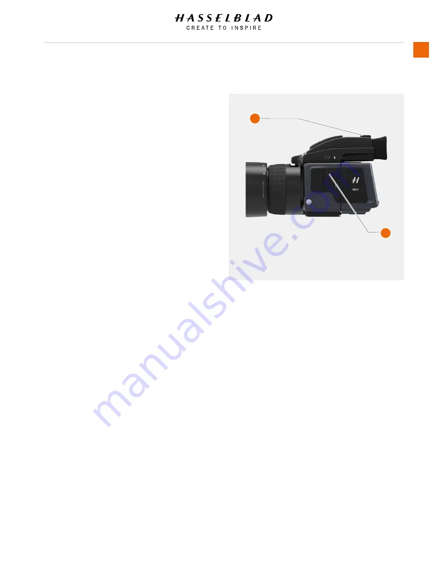
SEPARATE FLASH UNIT CONNECTION
Separate flash units can be electrically connected either by way
of the hot shoe accessory holder (see previous warnings) on the
top of the viewfinder (1) or via a cord to the PC connection port
(2) on the left hand side of the camera body. Slave unit switches
/ transmitters can also be connected on unit the (see specific
user manuals for details).
Keep the plastic safety cover in place in the hot shoe (1) when
not in use.
H6D
www.hasselblad.com
USER GUIDE
To Use
97
1 Hot Shoe
2 PC Connection Port
1
2
Summary of Contents for H6D
Page 1: ...Version 160421 v1 1 User Guide ...
Page 8: ...1 INTRODUCTION ...
Page 13: ...H6D www hasselblad com USER GUIDE Introduction 13 ...
Page 14: ...2 SAFETY ...
Page 17: ...3 OVERVIEW ...
Page 54: ...4 TO PREPARE ...
Page 66: ...5 TO USE ...
Page 83: ...H6D www hasselblad com USER GUIDE To Use 83 AUTOMATIC EXPOSURE P AND PV MODE ...
Page 171: ...6 ACCESSORIES ...
Page 186: ...7 TROUBLESHOOTING ...


