SECTION 1
GETTING ACQUAINTED
2
Front View
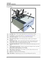
1.
Exit Roller Cover
– This cover plate must be removed to install the Service Station.
2.
Control Panel
– Provides printer controls. See “
Control Panel Functions
” section.
3.
Side Guide Locking Knob
– Used to secure the position of the side guide.
4.
Rear Media Support Guide –
Provides the proper angle to enhance paper feeding and
separation.
5.
Media Support Wedge –
Allows for adjustments in stack angle, based on media type and
length. Helps to force the media against the separation area. Narrow and wide wedges are
provided with the printer, to accommodate different media widths.
6.
Adjustable Media Side Guide –
Adjusts to hold the media against the Media Registration Side
Guide.
7.
Media Registration Side Guide–
All media is registered against this guide. It has two positions.
Inner position for media measuring 3” to 8.5” in width.
Outer position for media measuring 8.6” to 9.5” in width.
8.
Sheet Separator Locking Screws –
These thumb screws (four total) are used to secure the
positions of the four sheet separators.
9.
Top Cover –
Provides access to the Print Engine.
10.
Ink Tank Door –
Hinged door provides access to the Ink Tanks and Ink Waste Tray.
2
10
3
1
4
6
7
8
9
5


