INSTRUCTION MANUAL
N2600S SERIES NMX-ENC-N2612S ENCODER / NMX-DEC-N2622S
DECODER
NMX-ENC-N2612S, NMX-ENC-N2612S-C
NMX-ENC-N2622S
Page 1: ...INSTRUCTION MANUAL N2600S SERIES NMX ENC N2612S ENCODER NMX DEC N2622S DECODER NMX ENC N2612S NMX ENC N2612S C NMX ENC N2622S ...
Page 2: ...ected only to PoE networks without routing to the outside plant The exclamation point within an equilateral triangle is intended to alert the user to the presence of important operating and maintenance servicing instructions in the literature accompanying the product The lightning flash with arrowhead symbol within an equilateral triangle is intended to alert the user to the presence of uninsulate...
Page 3: ...in a residential installation This equipment generates uses and can radiate radio frequency energy and if not installed and used in accordance with the instructions may cause harmful interference to radio communications However there is no guarantee that interference will not occur in a particular installation If this equipment does cause harmful interference to radio or television reception which...
Page 4: ...the middle of the logo is the number of years of environmental utility Manufacturer Information HARMAN Professional Inc Address 8500 Balboa Blvd Northridge CA 91329 USA EU Regulatory Contact Harman Professional Denmark ApS Olof Palmes Allé 44 8200 Aarhus N Denmark UK Regulatory Contact Harman Professional Solutions 2 Westside London Road Apsley Hemel Hempstead HP3 9TD UK ...
Page 5: ...IP Addresses 19 Option 1 Assigning IP Addresses Individually using the Settings page 19 Option 2 Assigning IP Addresses to Multiple Units using CSV files 20 Step 5 Connecting Encoders to an Input Source 21 Switching and Scaling Options 22 Seamless Switching 22 Control Options 23 Primary Control Options 23 N Command Controllers 23 Third Party Controllers 23 N Act On Board Built In Control 23 KVM Co...
Page 6: ...53 Web Page Section General Setup 54 Security Certificates Section General Setup 55 User Security Details Section Users Setup 56 LDAP Section LDAP Setup 57 Control Page 58 Serial Commands Serial Setup 59 RS232 Settings Serial Setup 60 Serial Settings Serial Setup 61 IR Command IR Setup 62 IR Passthrough Settings IR Setup 63 KVM USB 2 0 Connection KVM USB 2 0 64 System Page 65 Command Log Log 66 De...
Page 7: ...tup 96 Security Certificates Section General Setup 97 User Security Details Section Users Setup 98 LDAP Section LDAP Setup 99 Control Page 100 Serial Commands Serial Setup 101 RS232 Settings Serial Setup 102 Serial Settings Serial Setup 103 IR Command IR Setup 104 IR Passthrough Settings IR Setup 105 USB Setting KVM USB 106 System Page 107 Command Log Log 108 Debug Log Log 109 Link Layer Discovery...
Page 8: ... H265 Stream from the N2612S Encoder allowing for maximum flexibility of the system USB 2 0 can be independently routable or follow video Output scaling performed at the Decoder for maximum flexibility Power over Ethernet PoE eliminates the need for a local power supply and speeds installation Units can still be powered locally by 12VDC This allows easy rack mountable high density installations In...
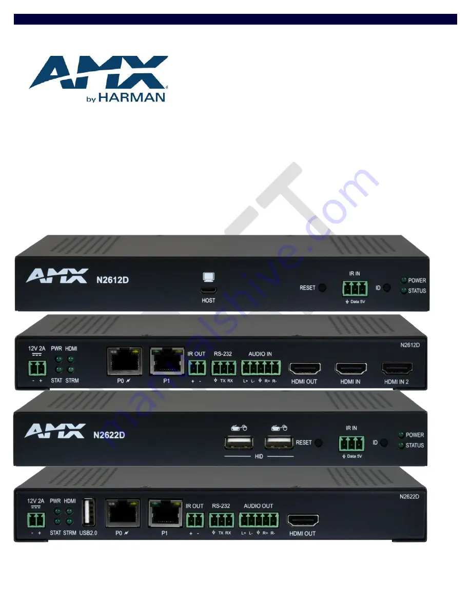
Page 9: ...e ID Discovery Button 5 Power Status Indicators 1 12VDC Input not needed with PoE 2 Status Indicators 3 USB 2 0 Standard A Port 4 RJ45 Auto Sensing Gigabit Ethernet Switch Port PoE 5 RJ45 Auto Sensing Gigabit Ethernet Switch Port FIG 4 N2622S Decoder Rear Panel 6 IR Emitter Output Connection 7 RS232 Connection 8 Analog Audio Output 9 HDMI Video Output 1 2 3 4 5 6 7 8 9 1 2 3 4 5 ...
Page 10: ...tware activity This activity is also shown by the STATLED on the rear panel Rear Panel 12V 2A 12 Volt DC power input PWR LED Same as POWER LED described above HDMI LED On green when an HDMI connection exists STAT LED Same as STATUS LED described above STRM LED On green when the unit is streaming video USB 2 0 Standard A port For USB 2 0 support Connect the Decoder to the USB 2 0 compatible device ...
Page 11: ...be less than 1Gb s NOTE PoE power is only supplied to the unit connected directly to the network All other units in the daisy chain must have an external power supply Video N2612S Encoders For video encoding of a digital source connect the source to the Encoder s HDMI 1 IN or HDMI 2 IN port using a video cable with an HDMI connector or adapter For local viewing of pass thru video connect a digital...
Page 12: ...ork on page 14 and Connecting Encoders to the Network and Configuring Stream Settings on page 15 for more information on these connections FIG 5 Installing Mounting Wings Rack Mounting N2600 Series Stand Alone Units A Rack Shelf part number N9102 accommodates up to two stand alone N Series Encoders or Decoders side by side mix and match FIG 6 Rack Mounting Stand Alone Units N2600 Series Cards A Ca...
Page 13: ...e Figure 8 FIG 8 Fully Populated Card Cage 6 For proper airflow cover any unused card slots with faceplate blanks Blanks are sold separately part number N9210 7 Make sure the Card Cage s power cord is plugged in for proper cooling CAUTION Keep the Card Cage s power cord plugged in at all times so that the internal fans are always running Not doing so could void the warranty of the cage and all ins...
Page 14: ...work segment or link Matrix switches as large as 1200x800 have been constructed on a house network using N Series equipment Alternatively many customers choose to deploy on physically separate networks in order to use low cost network appliances but keep video traffic separate from data and voice 3 N Able software has been loaded on the computer you are using to configure theequipment From your ho...
Page 15: ...Installing and Configuring Your AV Equipment N2612S N2622S Manual 15 4 Scroll down in the list to the Internet Protocol Version 4 option Highlight it and click the Properties button ...
Page 16: ...pter N2600 units support embedded audio input and output on the HDMI ports however some display devices e g many monitors do not support embedded audio When using such a display use the AUDIO port for separate transmission of sound and turn HDMI Audio off on the Settings page to avoid video display issues Power is supplied via a PoE enabled switch Refer to the following steps and Figure 9 for guid...
Page 17: ...onnect your N Series Encoder s P0 port to a PoE enabled switch NOTE In order for the unit to receive PoE it must be connected to a switch or other equipment that has a PoE PSE port 2 In N Able select the Unit Management tab and click the Auto Discover button if the table has not already populated itself with the installed units See Figure 10 FIG 10 Unit Management Page 3 Find your Encoder in the l...
Page 18: ... later on the Settings page Default username admin Default password password FIG 12 Login Page NOTE The Login page is only displayed if N Able s stored username password does not match the unit s username password A default system will match 5 The Settings page is displayed see Figure 13 6 Change the Stream setting We recommend setting Stream to a number between 2 and 254 it is required that the n...
Page 19: ...r being in the same IP address range as the N Series devices Therefore before making any N2600 IP address changes we recommend having two statically assigned IP addresses on your computer Configure the first IP address to be in the range of the default N Series IP settings i e in the 169 254 xxx xxx range AND Configure a second IP address in the range of the IP address you are planning to assign t...
Page 20: ...iple networked AV devices at the same time It can also provide valuable diagnostics by allowing you to see the last known device configuration as well as scan the network for new devices regardless of IP configuration To configure units using a CSV file follow these steps 1 Make sure that you have performed an Auto Discover on the Unit Management tab of N Able since connecting all of the new units...
Page 21: ...an now connect to the appropriate AV source s This connection from an Encoder HDMI IN port to an input source is accomplished using either an HDMI cable or DVI I through adapter 1 Connect the source you would like to use for the Encoder camera laptop etc to the Encoder s HDMI IN port using an HDMI cable This connection can be digital or analog 2 Repeat until all Encoders are connected to their sou...
Page 22: ...coder scaler is set to 1080p50 60 Any other attempts at downscaling are not recommended supported Seamless Switching The N2600 Series supports seamless switching capability if the scalers in the Decoders are all set to the same resolution and refresh rate If the scalers are off all of the sources must have the same resolution and refresh rate To get streams onto a Decoder use the Video Matrix tab ...
Page 23: ...PI available on our website N Act On Board Built In Control All N Series Encoders and Decoders have on board built in control capability via events that can trigger any number of TCP UDP commands to other IP controllable devices Included free with all N Series Encoders Decoders Available later 2023 via firmware update KVM Configuration The N2600 Encoders and Decoders are KVM capable By default KVM...
Page 24: ...ect the graphical user interface GUI From any main page in the GUI you can access all other main pages by clicking the links in the top navigation bar Figure 17 shows the navigation bar and provides hot links to the sections of this chapter which describe each mainpage Home Page on page 25 Network Page on 30 Video Audio on 39 Security on 53 Control on 58 System on 65 FIG 17 Section Links ...
Page 25: ...n Figure 18 This page is divided into several sections and has links to other dialog boxes for additional configuration options Refer to the following sections for detailed descriptions Stream Setup Settings Section on page 26 Management Setup Settings on page 27 Current Source Section on page 28 General Setup Section on page 29 FIG 18 Settings Page ...
Page 26: ...arly useful Some good examples are Lobby Left HDMI for left side of lobby HDMI input or CR201 HDMI for Conference Room 201 HDMI input Keep in mind the matrices are organized alphanumerically Stream View edit the current transmit stream number To better understand this setting think of Encoders more like a channel on a cable box rather than a traditional AV Matrix Each Encoder must have a unique st...
Page 27: ...Table 2 FIG 20 Management Setup Settings TABLE 2 Home Page Management Setup Settings Option Description Notes Settings Lock Enable to lock the Encoder IP settings and stream number preventing automated processes from N Able or N Command from occurring OSD Menu Enables the On Screen Display OSD for 10 seconds then turns off for 10 seconds The process repeats until disabled ...
Page 28: ...ly every 2 seconds Path MPJEG IP Address snapshot jpg Current Source Selectable field consisting of three options and selecting one of the drop downs will select that input source Auto Last source plugged in will be the active source HDMI HDMI In will be the active source USB C USB C In will be the active source There can only be one active source at a time Recommended to leave Auto selected for m...
Page 29: ...address specified here Status Interval sec Determines how often in seconds the unit transmits status packets Gratuitous ARP Enables the encoder to send a periodic address resolution protocol ARP packet to the network Arp Interval sec Determines how often in seconds the unit transmits gratuitous ARP packets Discovery Packet Transmit Enables the N Series multicast discovery service used to identify ...
Page 30: ...as links to other dialog boxes for additional configuration options Refer to the following sections for detailed descriptions MWC IP Setup Settings Section on page 31 H 26x IP Setup Settings Section on page 34 VLAN Setup on page 36 Date Time Section on page 37 802 1x Section on page 38 MWC IP Setup on page 31 H 26x IP Setup on page 34 VLAN Setup on page 36 Date Time on page 37 802 1x on page 38 FI...
Page 31: ...rk Page General Section of MWC IP Setup Option Description Notes Domain Type in the domain name of the network if needed DNS IP 1 IP address of a DNS server DNS IP 2 IP address of a DNS server DNS IP 3 IP address of a DNS server IGMP v3 Support Enable to allow for IGMP v3 support Save Pressed to save all information on the MWC IP Setup page and apply those settings Cancel Pressed to discard all se...
Page 32: ...or Static IP Address mode IP Address View the current IP address of the encoder When in Static mode enter an IP address into this field Subnet Mask View the current subnet mask address of the encoder When in Static mode enter a subnet mask address into this field Gateway View the current gateway address of the encoder When in Static mode enter a gateway address into this field Save Pressed to save...
Page 33: ... Enable Disable When enabled the unit will attempt to obtain a DHCP IPv6 address Disabled by default Requires an IPv6 DHCP server IPv6 Address View the current IPv6 address of the encoder IPv6 Subnet Mask View the current IPv6 subnet mask address of the encoder IPv6 Gateway View the current IPv6 gateway address of the encoder Save Pressed to save all information on the MWC IP Setup page and apply ...
Page 34: ... Section of H 26x IP Setup Option Description Notes Domain Type in the domain name of the network if needed DNS IP 1 IP address of a DNS server DNS IP 2 IP address of a DNS server DNS IP 3 IP address of a DNS server Port Assignment Drop down menu to specify which port the H 26x video is encoded on Save Pressed to save all information on the MWC IP Setup page and apply those settings Cancel Pressed...
Page 35: ...P or Static IP Address mode IP Address View the current IP address of the encoder When in Static mode enter an IP address into this field Subnet Mask View the current subnet mask address of the encoder When in Static mode enter a subnet mask address into this field Gateway View the current gateway address of the encoder When in Static mode enter a gateway address into this field Save Pressed to sa...
Page 36: ...BLE 10 Network Page Date Time Option Notes Video VLAN Tagging Allow Multicast Options to allow or disallow multicast on the selected port If multicast is disallowed then no video will be present on that port Disable P1 When enabled will cause P1 to be turned off Save Pressed to save all information on the page and apply those settings Cancel Pressed to discard all settings made on the page ...
Page 37: ...ABLE 11 Network Page Date Time Option Description Notes Current Date and Time Displays the current date and time of the unit Time Zone Used to select the offset for the NTPP time Select Used to select the NTP server connection Edit When selected will allow editing of that name server information Add Server When selected will open a pop up allowing to input information for the NTP server ...
Page 38: ...d Select one of the options listed EAP TLS Certificate or EAP MSCHAP V2 Password to connect to the 802 1x server Domain Type the name of the domain the 802 1x server will be connecting Username Type the username here to access the 802 1x Field is used when the Authentication Method is EAP MSCHAP V2 Password Password Type the password here to access the 802 1x Field is used when the Authentication ...
Page 39: ...in Figure 32 This page is divided into several sections and has links to other dialog boxes for additional configuration options Refer to the following sections for detailed descriptions Video Settings on page 40 Audio Settings on page 51 EDID Settings on page 52 Video Settings on page 40 Audio Settings on page 51 EDID Settings on page 52 FIG 32 Video Audio Page ...
Page 40: ...otes TX Enable When enabled will allow the encoder to transmit multicast video through the network Disable HDCP Advertising When enabled will cause the encoder to not send HDCP advertisements Video Source Status field displaying one of three options showing the current input source Auto Last source plugged in will be the active source HDMI 1 HDMI In 1 will be the active source HDMI 2 HDMI In 2 wil...
Page 41: ...LE 14 Video Audio Current Source section of the Video tab Option Description Notes Current Source Status field displaying one of three options showing the current input source Auto Last source plugged in will be the active source HDMI 1 HDMI 1 In will be the active source HDMI 2 HDMI 2 In will be the active source Preview Image When Preview Image is enabled will display a snapshot of the current i...
Page 42: ...31 Options are described in Table 12 FIG 35 Stream Video Section TABLE 15 Video Audio Stream Video section of the H 26x section of the Video tab Option Description Notes TX Enable When enabled will allow the encoder to transmit H 26x video through the network H 26x Mode Drop down menu with options of H 264 and H 265 H 26x Profile Drop down menu with options to select a preset profile of YouTube Pa...
Page 43: ...able options change depending on the H 26x Profile chosen Stream URL User editable field used to enter the address of where to transmit the H 26x stream Stream Key User editable field used to enter the stream key Max Video Bitrate Maximum video bitrate in kbps to send the video stream to the URL provided Max Audio Bitrate Maximum audio bitrate in kbps to send the audio stream to the URL provided K...
Page 44: ...hown in Figure 31 Options are described in Table 12 FIG 37 General Section TABLE 17 Video Audio General section of the HDMI Pass thru section of the Video tab Option Description Notes HDMI Pass Thru When enabled will allow video to transmitted out of the HDMI Output YUV Output Drop down menu with options of Auto On and Off Video Mute When enabled will allow the video to be muted on the HDMI Output...
Page 45: ...ideo Audio page is shown in Figure 31 Options are described in Table 12 FIG 38 Current Source Section TABLE 18 Video Audio Current Source section of the HDMI Pass thru section of the Video tab Option Description Notes Preview Image When Preview Image is enabled will display a snapshot of the current input source Clicking on the preview image will open a pop up showing a larger preview image ...
Page 46: ... 31 Options are described in Table 12 FIG 39 Status Section TABLE 19 Video Audio Status section of the HDMI Pass thru section of the Video tab Option Description Notes HDMI Pass Thru Status Status field displaying connection status of the HDMI Out port Disconnected HDMI cable is not detected Connected HDMI cable is detected HDMI Pass Thru Resolution Current resolution of the video stream on the HD...
Page 47: ...o page is shown in Figure 31 Options are described in Table 12 FIG 40 General Section TABLE 20 Video Audio General section of the HDMI In 1 section of the Video tab Option Description Notes Active EDID Prefer Resolution Displays the current preferred resolution being detected by EDID Disable HDCP Advertising When enabled will cause the encoder to not send HDCP advertisements ...
Page 48: ...gure 31 Options are described in Table 12 FIG 41 Status Section TABLE 21 Video Audio Status section of the HDMI In 1 section of the Video tab Option Description Notes HDMI 1 Status Status field displaying connection status of the HDMI In 1 port Disconnected HDMI cable is not detected Connected HDMI cable is detected HDMI 1 Resolution Current resolution of the video stream on the HDMI In 1 port ...
Page 49: ...o page is shown in Figure 31 Options are described in Table 12 FIG 42 General Section TABLE 22 Video Audio General section of the HDMI In 2 section of the Video tab Option Description Notes Active EDID Prefer Resolution Displays the current preferred resolution being detected by EDID Disable HDCP Advertising When enabled will cause the encoder to not send HDCP advertisements ...
Page 50: ...gure 31 Options are described in Table 12 FIG 43 Status Section TABLE 23 Video Audio Status section of the HDMI In 2 section of the Video tab Option Description Notes HDMI 2 Status Status field displaying connection status of the HDMI In 2 port Disconnected HDMI cable is not detected Connected HDMI cable is detected HDMI 2 Resolution Current resolution of the video stream on the HDMI In 2 port ...
Page 51: ...oming from the HDMI input Analog Play audio coming from the Analog audio input Audio Mute When enabled will mute the audio for the audio source selected above HDMI Downmix Enable When enabled will allow the source audio to be downmixed Center Gain Gain level adjustment from 50 to 50 Front Gain Gain level adjustment from 50 to 50 Surround Gain Gain level adjustment from 50 to 50 Near Surround Gain ...
Page 52: ... thru Displays EDID information connected to the encoder s HDMI Pass thru Decode Click to translate the EDID currently displayed on the left to the operating parameters list on the right Encode After making any changes to the operating parameters list on the right click this button to update the EDID information on the left To store the new settings click Set EDID Read EDID Click to initially show...
Page 53: ...wn in Figure 46 This page is divided into several sections and has links to other dialog boxes for additional configuration options Refer to the following sections for detailed descriptions General Settings Section on page 54 Users Settings on page 56 LDAP Settings on page 57 General Setup on page 54 Users on page 56 LDAP on page 57 FIG 46 Security Page ...
Page 54: ...e via API call will need to use secure socket connections Command Secure Ports Only If enabled commands must be sent using secure sockets TLS SSL and follow the secure command port protocol Change Command Password Set the default password for command encryption When issuing API commands this password must precede each command in the format password r command Change Stream Encryption Password Set t...
Page 55: ...icates Section TABLE 27 Security Page Security Certificates Section of General Option Description Notes Type of Certificate Three options exist for the drop down CA Certificate Client Certificate Server Certificate Private Key Browse for the Private Key file Certificate Browse for the certificate file Password If required input password for the Private Key or Certificate file Upload Pressed to upl...
Page 56: ...Table 17 FIG 49 User Security Details Section TABLE 28 Security Page User Security Details Section of Users Option Description Notes New Password Input the new password for the Administrator account Confirm Password Input the new password for the Administrator account Accept Press to confirm and apply new password to the user account Cancel Press to discard changes and retain old password for the ...
Page 57: ... server LDAP LDAPS URL Address and port of the LDAP Server If using LDAP type ldap IP Port If using LDAPS type ldaps IP Port LDAP LDAPS Base DN Location of the BIND DN user account with the AD structure BIND DN The binding account being used to form the LDAP connection User Query Attr Search Password Password used for the BIND DN account Configure Certificate Pressed will redirect to the certifica...
Page 58: ...ge shown in Figure 39 This page is divided into several sections and has links to other dialog boxes for additional configuration options Refer to the following sections for detailed descriptions Serial Settings on page 59 IR Settings on page 62 KVM USB Settings on page 64 Serial on page 59 IR on page 62 KVM USB 2 0 on page 64 FIG 51 Control Page ...
Page 59: ...rial Option Description Notes New Will open a pop up window where new commands can be stored on the device Execute Once a command is selected from the list of commands and pressing execute Any response will be shown in the response box Delete Once a command is selected from the list of command and pressing delete will remove that command from the list Edit Once a command is selected from the list ...
Page 60: ...232 Settings Section TABLE 31 Control Page RS232 Settings Section of Serial Option Description Notes RS232 Baud Rate Select the drop down and choose from the various baud rates RS232 Data Bits Select the drop down and choose from the various data bits RS232 Parity Select the drop down and choose from the various parity options RS232 Stop Bits Select the drop down and choose from the various stop b...
Page 61: ...Control page is shown in Figure 74 Options are described in Table 46 FIG 54 Serial Settings Section TABLE 32 Control Page Serial Settings Section of Serial Option Description Notes Serial Main Enable Enables the device to be the server to the designated client Serial Secondary Address Enter the IP address of the serial client device ...
Page 62: ...ption Description Notes New Will open a pop up window where new commands can be stored on the device Execute Once a command is selected from the list of commands and pressing execute will transmit that command Delete Once a command is selected from the list of command and pressing delete will remove that command from the list Edit Once a command is selected from the list of commands and pressing e...
Page 63: ...e is shown in Figure 76 Options are described in Table 48 FIG 56 IR Passthrough Settings Section TABLE 34 Control Page IR Passthrough Section of IR Option Description Notes IR Passthrough Enable Enables support for passing IR input from one unit to the IR output of another IR Client IP Specify the IP address of the unit to send the IR passthrough data ...
Page 64: ...n the Control page is shown in Figure 40 Options are described in Table 19 FIG 57 KVM USB 2 0 Settings Section TABLE 35 Control Page KVM USB 2 0 Settings Section of USB Option Description Notes USB 2 0 Enable When enabled will allow a decoder USB 2 0 signal to be received KVM Enable When enabled will allow a decoder KVM signal to be received ...
Page 65: ... pages to access the page shown in Figure 41 This page is divided into several sections and has links to other dialog boxes for additional configuration options Refer to the following sections for detailed descriptions Logs Section on page 66 Status Settings on page 68 Logs on page 66 Status on page 68 FIG 58 System Page ...
Page 66: ...he Command Log section of the Log on the System page is shown in Figure 42 Options are described in Table 20 FIG 59 Command Log Section TABLE 36 System Page Command Log Section of Log Option Description Notes Reset Logs When pressed will cleat the Command Log history table ...
Page 67: ... are described in Table 21 FIG 60 Debug Log Section TABLE 37 System Page Debug Log Section of Log Option Description Notes Start Debug Log When pressed will begin enhanced log gathering Used when troubleshooting an issue with tech support End Debug Log When pressed will stop enhanced log gathering Used when troubleshooting an issue with tech support ...
Page 68: ...22 FIG 61 LLDP Section TABLE 38 System Page LLDP Section of Status Option Description Notes Switch Mac Mac address of the network switch Switch Name Name of the network switch Switch Description Network description of the switch Port Number Port number the device is connected Description Network port description Vlan ID Vlan of the network device is connected PoE Watts being supplied to the device...
Page 69: ... resolution detected on the HDMI Input USB C Status Displays the status of the USB C input as either Connected or Disconnected USB C Resolution Displays the resolution detected on the USB C Input HDCP Status Reports status of HDCP along with version information Port 50001 Source IP IP address of the device connected to the port Port 50002 Source IP Serial Source IP KVM IP USB 2 0 IP Port P0 Displa...
Page 70: ...E 40 System Page Current Source of Status Option Description Notes Current Source Displays the current source selected Auto Last source plugged in will be the active source HDMI HDMI In will be the active source USB C USB C In will be the active source Preview Area When Preview Image is enabled will display a snapshot of the current input source Clicking on the preview image will open a pop up sho...
Page 71: ... serial number of the Encoder Mac Address Displays the MAC address of the network interface of the Encoder Firmware Version Displays the date code for the currently running version of the Encoder internal firmware Web Version Displays the date code for the currently running version of the web interface Default Settings Click to restore the device to the original factory settings This resets everyt...
Page 72: ... interface GUI As explained previously in the Encoder Configuration Options section on page 24 you can access the GUI main pages by clicking the links in the top navigation bar Below shows the navigation bar and provides hot links to the sections of this chapter which describe each main page Home Page on page 53 Network Page on 58 Video Audio Page on 64 Security Page on 70 Control Page on 75 Syste...
Page 73: ...n Figure 65 This page is divided into several sections and has links to other dialog boxes for additional configuration options Refer to the following sections for detailed descriptions Stream Setup Settings Section on page 54 Management Setup Settings on page 55 Current Source Section on page 56 General Setup Section on page 57 FIG 65 Settings Page ...
Page 74: ... useful Some good examples are Lobby Left HDMI for left side of lobby HDMI input or CR201 HDMI for Conference Room 201 HDMI input Keep in mind the matrices are organized alphanumerically Receive Source Drop down menu containing the options of MWC or H 26x Video Stream View edit the current receive video stream number Audio Stream View edit the current receive audio stream number Audio Follows Vide...
Page 75: ...able 43 FIG 67 Management Setup Settings TABLE 43 Home Page Management Setup Settings Option Description Notes Settings Lock Enable to lock the Decoder IP settings and stream number preventing automated processes from N Able or N Command from occurring OSD Menu Enables the On Screen Display OSD for 10 seconds then turns off for 10 seconds The process repeats until disabled ...
Page 76: ...ction Option Description Notes Preview Image When enabled the current source will be shown in the below image preview area The preview image is updated approximately every 2 seconds Receive Source Displays the current receiving source The options are MWC or H 26x Video Preview Area When Preview Image is enabled will display a snapshot of the current output source Clicking on the preview image will...
Page 77: ...to the Send Status Address listed Send Status Address When Enable Send Status is enabled the encoder sends a periodic status packet to the IP address specified here Status Interval sec Determines how often in seconds the unit transmits status packets Gratuitous ARP Enables the encoder to send a periodic address resolution protocol ARP packet to the network Arp Interval sec Determines how often in ...
Page 78: ...as links to other dialog boxes for additional configuration options Refer to the following sections for detailed descriptions MWC IP Setup Settings Section on page 79 H 26x IP Setup Settings Section on page 82 VLAN Setup on page 84 Date Time Section on page 85 802 1x Section on page 86 MWC IP Setup on page 79 H 26x IP Setup on page 82 VLAN Setup on page 84 Date Time on page 85 802 1x on page 86 FI...
Page 79: ...ork Page General Section of MWC IP Setup Option Description Notes Domain Type in the domain name of the network if needed DNS IP 1 IP address of a DNS server DNS IP 2 IP address of a DNS server DNS IP 3 IP address of a DNS server IGMP v3 Support Enable to allow for IGMP v3 support Save Pressed to save all information on the MWC IP Setup page and apply those settings Cancel Pressed to discard all s...
Page 80: ...CP or Static IP Address mode IP Address View the current IP address of the encoder When in Static mode enter an IP address into this field Subnet Mask View the current subnet mask address of the encoder When in Static mode enter a subnet mask address into this field Gateway View the current gateway address of the encoder When in Static mode enter a gateway address into this field Save Pressed to s...
Page 81: ...tes Enable Disable When enabled the unit will attempt to obtain a DHCP IPv6 address Disabled by default Requires an IPv6 DHCP server IPv6 Address View the current IPv6 address of the encoder IPv6 Subnet Mask View the current IPv6 subnet mask address of the encoder IPv6 Gateway View the current IPv6 gateway address of the encoder Save Pressed to save all information on the MWC IP Setup page and app...
Page 82: ...l Section of H 26x IP Setup Option Description Notes Domain Type in the domain name of the network if needed DNS IP 1 IP address of a DNS server DNS IP 2 IP address of a DNS server DNS IP 3 IP address of a DNS server Port Assignment Drop down menu to specify which port the H 26x video is encoded on Save Pressed to save all information on the MWC IP Setup page and apply those settings Cancel Presse...
Page 83: ...CP or Static IP Address mode IP Address View the current IP address of the encoder When in Static mode enter an IP address into this field Subnet Mask View the current subnet mask address of the encoder When in Static mode enter a subnet mask address into this field Gateway View the current gateway address of the encoder When in Static mode enter a gateway address into this field Save Pressed to s...
Page 84: ...ABLE 51 Network Page Date Time Option Notes Video VLAN Tagging Allow Multicast Options to allow or disallow multicast on the selected port If multicast is disallowed then no video will be present on that port Disable P1 When enabled will cause P1 to be turned off Save Pressed to save all information on the page and apply those settings Cancel Pressed to discard all settings made on the page ...
Page 85: ...9 Options are described in Table 52 FIG 79 Date Time Section TABLE 52 Network Page Date Time Option Description Notes Select Used to select the NTP server connection Edit When selected will allow editing of that name server information Add Server When selected will open a pop up allowing to input information for the NTP server ...
Page 86: ...d Select one of the options listed EAP TLS Certificate or EAP MSCHAP V2 Password to connect to the 802 1x server Domain Type the name of the domain the 802 1x server will be connecting Username Type the username here to access the 802 1x Field is used when the Authentication Method is EAP MSCHAP V2 Password Password Type the password here to access the 802 1x Field is used when the Authentication ...
Page 87: ...in Figure 81 This page is divided into several sections and has links to other dialog boxes for additional configuration options Refer to the following sections for detailed descriptions Video Settings on page 88 Audio Settings on page 68 EDID Settings on page 69 Video Settings on page 88 Audio Settings on page 68 EDID Settings on page 69 FIG 81 Video Audio Page ...
Page 88: ...io Stream Video section of the MWC Stream section of the Video tab Option Description Notes Receive Source Drop down to select MWC or H 26x for the type of stream to receive The unit can only receive MWC or H 26x at a time The unit can not receive both at the same time Video Stream View edit field to input the MWC stream to be decoded Only shown when the MWC is selected Stream URL View edit field ...
Page 89: ...f the Video tab Option Description Notes Current Source Status field displaying one of three options showing the current input source Auto Last source plugged in will be the active source HDMI 1 HDMI 1 In will be the active source HDMI 2 HDMI 2 In will be the active source Preview Image When Preview Image is enabled will display a snapshot of the current input source Clicking on the preview image ...
Page 90: ...caler The scaler must be enabled for the selected resolution to be used Video Mute Used to Mute the video from the HDMI output Last Frame Hold When enabled will cause the decoder to hold the last video frame received before the loss of stream occurred Implemented via firmware later HDMI Off on Stream Loss When enabled will cause the HDMI output to be disabled if the stream is lost HDMI Off Delay T...
Page 91: ...igure 86 Options are described in Table 57 FIG 86 CEC Settings Section TABLE 57 Video Audio CEC Settings section of the HDMI Out section of the Video tab Option Description Notes Manual CEC Power Manual Power On Off Allows for control of CEC Power over the HDMI cable with monitors equipped and enabled to support the CEC Protocol On When pressed will turn the monitor on Off When pressed will turn t...
Page 92: ...nt Source section of the Video tab Option Description Notes HDMI Out Status Status of the HDMI Output as Connected HDMI signal detected on the HDMI Output Disconnected No HDMI signal detected on the HDMI Output HDMI Out Resolution Output Resolution being sent to the display HDCP Status Current status of the HDCP flag being detected Preview Image When Preview Image is enabled will display a snapsho...
Page 93: ... of the Audio on the Video Audio page is shown in Figure 88 Options are described in Table 59 FIG 88 Audio Section TABLE 59 Network Page Audio Section of Audio Setup Option Description Notes Audio Source Audio source to be output HDMI ANALOG Audio Mute When enabled will cause the audio to be muted ...
Page 94: ...LE 60 Video Page EDID Section of EDID Setup Option Description Notes EDID drop down Select EDID information to display Decode Click to translate the EDID currently displayed on the left to the operating parameters list on the right Encode After making any changes to the operating parameters list on the right click this button to update the EDID information on the left To store the new settings cli...
Page 95: ...wn in Figure 90 This page is divided into several sections and has links to other dialog boxes for additional configuration options Refer to the following sections for detailed descriptions General Settings Section on page 71 Users Settings on page 73 LDAP Settings on page 74 General Setup on page 71 Users on page 73 LDAP on page 74 FIG 90 Security Page ...
Page 96: ...e via API call will need to use secure socket connections Command Secure Ports Only If enabled commands must be sent using secure sockets TLS SSL and follow the secure command port protocol Change Command Password Set the default password for command encryption When issuing API commands this password must precede each command in the format password r command Change Stream Encryption Password Set t...
Page 97: ...icates Section TABLE 62 Security Page Security Certificates Section of General Option Description Notes Type of Certificate Three options exist for the drop down CA Certificate Client Certificate Server Certificate Private Key Browse for the Private Key file Certificate Browse for the certificate file Password If required input password for the Private Key or Certificate file Upload Pressed to upl...
Page 98: ...Table 63 FIG 93 User Security Details Section TABLE 63 Security Page User Security Details Section of Users Option Description Notes New Password Input the new password for the Administrator account Confirm Password Input the new password for the Administrator account Accept Press to confirm and apply new password to the user account Cancel Press to discard changes and retain old password for the ...
Page 99: ... server LDAP LDAPS URL Address and port of the LDAP Server If using LDAP type ldap IP Port If using LDAPS type ldaps IP Port LDAP LDAPS Base DN Location of the BIND DN user account with the AD structure BIND DN The binding account being used to form the LDAP connection User Query Attr Search Password Password used for the BIND DN account Configure Certificate Pressed will redirect to the certifica...
Page 100: ...ge shown in Figure 95 This page is divided into several sections and has links to other dialog boxes for additional configuration options Refer to the following sections for detailed descriptions Serial Section on page 78 IR Settings on page 79 KVM USB Settings on page 81 Serial Setup on page 78 IR on page 79 KVM USB on page 81 FIG 95 Control Page ...
Page 101: ...erial Option Description Notes New Will open a pop up window where new commands can be stored on the device Execute Once a command is selected from the list of commands and pressing execute Any response will be shown in the response box Delete Once a command is selected from the list of command and pressing delete will remove that command from the list Edit Once a command is selected from the list...
Page 102: ...232 Settings Section TABLE 66 Control Page RS232 Settings Section of Serial Option Description Notes RS232 Baud Rate Select the drop down and choose from the various baud rates RS232 Data Bits Select the drop down and choose from the various data bits RS232 Parity Select the drop down and choose from the various parity options RS232 Stop Bits Select the drop down and choose from the various stop b...
Page 103: ...Control page is shown in Figure 98 Options are described in Table 67 FIG 98 Serial Settings Section TABLE 67 Control Page Serial Settings Section of Serial Option Description Notes Serial Main Enable Enables the device to be the server to the designated client Serial Secondary Address Enter the IP address of the serial client device ...
Page 104: ...Option Description Notes New Will open a pop up window where new commands can be stored on the device Execute Once a command is selected from the list of commands and pressing execute will transmit that command Delete Once a command is selected from the list of command and pressing delete will remove that command from the list Edit Once a command is selected from the list of commands and pressing ...
Page 105: ... is shown in Figure 100 Options are described in Table 69 FIG 100 IR Passthrough Settings Section TABLE 69 Control Page IR Passthrough Section of IR Option Description Notes IR Passthrough Enable Enables support for passing IR input from one unit to the IR output of another IR Client IP Specify the IP address of the unit to send the IR passthrough data ...
Page 106: ... Description Notes KVM Enable When enabled will allow the decoder to connect to the encoder listed in the IP Address field for KVM USB 2 0 Enable When enabled will allow the decoder to connect to the encoder listed in the IP Address field for USB 2 0 IP Address View edit field of what encoder to connect the decoder Switch When executed will cause the decoder to connect to the encoder listed Discon...
Page 107: ... pages to access the page shown in Figure 102 This page is divided into several sections and has links to other dialog boxes for additional configuration options Refer to the following sections for detailed descriptions Logs Section on page 84 Status Settings on page 86 Logs on page 84 Status on page 86 FIG 102 System Page ...
Page 108: ...e Command Log section of the Log on the System page is shown in Figure 103 Options are described in Table 71 FIG 103 Command Log Section TABLE 71 System Page Command Log Section of Log Option Description Notes Reset Logs When pressed will cleat the Command Log history table ...
Page 109: ... are described in Table 72 FIG 104 Debug Log Section TABLE 72 System Page Debug Log Section of Log Option Description Notes Start Debug Log When pressed will begin enhanced log gathering Used when troubleshooting an issue with tech support End Debug Log When pressed will stop enhanced log gathering Used when troubleshooting an issue with tech support ...
Page 110: ... 73 FIG 105 LLDP Section TABLE 73 System Page LLDP Section of Status Option Description Notes Switch Mac Mac address of the network switch Switch Name Name of the network switch Switch Description Network description of the switch Port Number Port number the device is connected Description Network port description Vlan ID Vlan of the network device is connected PoE Watts being supplied to the devi...
Page 111: ...also be enabled for output resolution to work Downscaling is supported only if the input stream is 3840x2160 and the scaler is set to 1080P Any other attempts at downscaling are not recommended supported HDCP Status Reports status of HDCP along with version information Port 50001 Source IP IP address of the device connected to the port Port 50002 Source IP Serial Source IP KVM IP USB 2 0 IP Port P...
Page 112: ...nt Source of Status Option Description Notes Current Source Status field displaying one of three options showing the current input source Auto Last source plugged in will be the active source HDMI 1 HDMI 1 In will be the active source HDMI 2 HDMI 2 In will be the active source Preview Image When Preview Image is enabled will display a snapshot of the current input source Clicking on the preview im...
Page 113: ...number of the N2612 Encoder Mac Address Displays the MAC address of the network interface of the N2612 Encoder Firmware Version Displays the date code for the currently running version of the N2612 Encoder internal firmware Web Version Displays the date code for the currently running version of the web interface Default Settings Click to restore the device to the original factory settings This res...
Page 114: ...er is on Black screen no screen displays Set Decoder to LocalPlay If the LocalPlay screen does not appear check the display input settings and cabling As mentioned previously in this table you can change to the Local mode on the Decoder s Settings page If LocalPlay appears set Decoder to Live play mode and verify network is configured properly If screen is black with a slight sparkle effect verify...
Page 115: ...g this screen means that the Decoder CAN communicate with the Encoder across the network It is a good way to troubleshoot network communication between segments using only Encoders and Decoders without the need for source video into an Encoder NOTE If you see can see the HostPlay screen but cannot see live video this could mean that the Encoder and Decoder are not on the same subnet FIG 110 Local ...
Page 116: ...played when Decoder and Encoder Notes is receiving a stream from an Encoder is connected to a monitor that does NOT support Restricted Content i e the monitor is NOT HDCP compliant is transmitting HDCP protected content to the Decoder Once the Decoder detects that the monitor is not HDCP compliant this screen is displayed If you suspect that this message was displayed in error please call Technica...
Page 117: ... stream from an encoder it cannot decrypt Make sure the decoder has the correct password for decrypting the stream To reset the password go to the security page on both the encoder and decoder and click the reset button Refer to the security page section if you are not sure where to find this setting ...
Page 118: ...g on switch manufacturer Immediate Leave breaks any daisy chaining of multiple units together with a single home run therefore you will not be able to have both Immediate Leave units and daisy chaining on the same VLAN NOTE If Immediate Leave is disabled set IGMP Robustness to Default 2 Robustness can be adjusted generally from 2 10 The higher the value the more leave latency is added Warnings Not...
Page 119: ... Yes Yes No No 3440x1440 50 Yes Yes Yes No No 3440x1440 30 Yes Yes Yes No No 3440x1440 29 Yes Yes Yes No No 3440x1440 24 Yes Yes Yes No No 3440x1440 23 Yes Yes Yes No No 3840x1080 DFHD 60 Yes Yes Yes No No 3840x1080 59 Yes Yes Yes No No 3840x1080 50 Yes Yes Yes No No 3840x1080 30 Yes Yes Yes No No 3840x1080 29 Yes Yes Yes No No 3840x1080 24 Yes Yes Yes No No 3840x1080 23 Yes Yes Yes No No 1920x120...
Page 120: ... Interlaced 1360x768 60 Yes Yes Yes No No 1280x1024 60 Yes Yes Yes No No 1280x960 60 Yes Yes Yes No No 1280x800 60 Yes Yes Yes No No 1280x768 60 Yes Yes Yes No No 1280x720 HD 60 Yes Yes Yes No No 1280x720 59 Yes Yes Yes No No 1280x720 50 Yes Yes Yes No No 1024x768 60 Yes Yes Yes No No ...
Page 121: ...marks registered trademarks of their respective companies AMX does not assume responsibility for errors or omissions AMX also reserves the right to alter specifications without prior notice at any time The AMX Warranty and Return Policy and related documents can be viewed downloaded at www amx com 3000 RESEARCH DRIVE RICHARDSON TX 75082 AMX com 800 222 0193 469 624 8000 1 469 624 7400 fax 469 624 7...