


SYSTEM CONFIGURATION
SYSTEM CONFIGURATION
Remember that the test tone will circulate to all
seven channels; you simply won’t hear any sound
when it reaches the right surround back channel.
Harman Kardon strongly recommends that you
upgrade your speaker system to a 7.1-channel
package as soon as you can to achieve the best
possible reproduction of all surround programs.
If you have already completed an automated setup
using EzSet/EQ the settings calculated during that pro-
cedure will already appear. No further adjustment is
required unless you wish to change a specific item to
reflect your personal taste or a nonstandard system
configuration.
Before beginning the output level adjustment process,
make certain that all speaker connections have been
properly made. Set the system volume to the level that
you will use during a typical listening session.
Using the Full-OSD System
Follow these steps while seated in the listening posi-
tion that will be used most often:
1. Adjust the volume so that it is at
-15dB
, as
shown in the on-screen display or
Lower
Display Line
ı
.
2. If you have not run EzSet/EQ, make certain that
all speaker positions have been properly config-
ured for their
LARGE
or
SMALL
settings
(as outlined above).
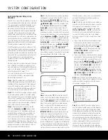
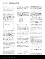
3. Output level adjustment is most easily done
through the
CHANNEL ADJUST
sub-
menu (Figure 15). If you are already at the
MASTER MENU
, press the
¤
Button
n
until the on-screen
›
cursor is next to the
MANUAL SETUP
line. Press the
Set
Button
p
to enter the
MANUAL SETUP
submenu, and then scroll down using the
¤
Button
n
until the
›
cursor is pointing
to the
CHANNEL ADJUST
line.
Press the
Set Button
p
again, and the
CHANNEL ADJUST
submenu will
appear (see Figure 15).
Figure 15
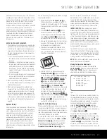
When the
CHANNEL ADJUST
submenu
first appears, the test tone is off. If desired, you
may immediately use the
¤
Button
n
to
select any channel for adjustment using an exter-
nal source, such as a test disc, from which to
judge the output levels. After the
›
cursor is
pointing to the channel to be adjusted, press the
‹
/
›
Buttons
o
to raise or lower the output
level. However, before proceeding with any man-
ual adjustment we recommend that you first use
the AVR’s internal test tone generator and auto-
matic sequencer to send a tone to each channel
so that you may verify that all speaker connec-
tions have been properly made.
4. To turn the test tone on and have it automatically
circulate among the channels where a speaker
has been configured (see page 28), press the
¤
Button
n
until the
›
cursor is pointing to
the
TEST TONE SEQ
line on the menu.
Next, press the
‹
/
›
Buttons
o
until
AUTO
is shown. The test tone will immediately begin to
circulate clockwise around the room, playing for
two seconds in each speaker before switching
to the next speaker position. The
›
cursor will
blink next to the active speaker to indicate which
speaker the sound should be coming from.
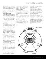
As the test noise circulates, listen to make certain
that the sound comes from the speaker position
shown in the
Lower Display Line
Q
, next to
the
›
cursor in the on-screen display, and by
the flashing indication in the
Speaker/Channel
Input Indicators
O
. If the sound from a speaker
location does NOT match the position indicated in
the display, turn the AVR 340 off using the
Main
Power Switch
1
and check the speaker wiring
or connections to external power amplifiers to
make certain that each speaker is connected to
the correct output terminal.
5. After checking for speaker placement, let the test
noise circulate again, and listen to see which
channels sound louder than the others. Using
the front left speaker as a reference, press the
‹
/
›
Buttons
o
on the remote to bring all
speakers to the same volume level. When one of
the
‹
/
›
Buttons
o
is pushed, the test noise
circulation will pause on the channel being adjust-
ed to give you time to make the adjustment.
When you release the button, the circulation will
resume after five seconds.
6. Continue to adjust the individual channels until the
volume level sounds the same from each speaker.
Adjustments should be made only with the
‹
/
›
Buttons
o
on the remote, NOT the main volume
controls. If you are using a sound-pressure level
(SPL) meter for precise level adjustment, set the
volume so that the meter reads 75dB on the C-
Weighting, Slow scale.
You may also make these same adjustments with
complete manual control over the channel being
adjusted by pressing the
¤
Button
n
until the
›
cursor is pointing to the
TEST TONE SEQ
line
on the menu and then using the
‹
/
›
Buttons
o
to select
MANUAL
. In the
MANUAL
mode, the
test tone will also start immediately, but the tone will
only be moved to another channel by pressing the
¤
Button
n
. When the manual sequencing mode is
active, the tone is turned off by pressing the
¤
Button
n
until the
›
cursor is pointing to the
TEST TONE
line and the
‹
/
›
Buttons
o
are then pressed to select
OFF
.
If you find that the output levels are either uncomfort-
ably low or high, you may repeat the procedure.
Return to Step 2 and adjust the master volume either
slightly higher or lower to accommodate your particu-
lar room layout and your tastes. You may repeat this
procedure as many times as necessary to achieve
a desired result. In order to prevent possible damage
to your hearing or your equipment, we emphasize
that you should avoid setting the master volume
above 0dB.
When all channels have an equal volume level, the
adjustment is complete. Use the
⁄
/
¤
Buttons
n
to move the
›
cursor next to the
TEST TONE
line, and press the
‹
/
›
Buttons
o
until the word
OFF
appears to stop the test tone.
Note that any time a given surround mode is selected,
even for a different source input, these output level
settings will be used. However, the output levels must
be set independently for each surround mode, includ-
ing variations such as Dolby Pro Logic II-Movie versus
Dolby Pro Logic II-Music. Although this may seem to
be tedious, it is necessary in order to optimize the
AVR’s performance when differing methods are
employed to steer the audio materials to the various
channels. However, the AVR will carry over the settings
for one mode to the same mode in a different channel
configuration, such as Dolby Pro Logic IIx-Movie and
Dolby Pro Logic II-Movie. If you wish, as a shortcut to
get started quickly, you may set the levels for Dolby
Pro Logic IIx-Movie and copy down those settings, re-
entering them for each of the Dolby modes and enter-
ing the settings only for those speakers which are
available for each mode. Later, it is recommended that
you adjust the output levels while listening to various
sources, as opposed to the test tone. See page 42
for more information on trimming the output levels
to external source material.
To exit this menu, press the
⁄
/
¤
Buttons
n
until
the on-screen
›
cursor is next to the
BACK TO
MASTER
MENU
line, and then press the
Set
Button
p
to return to the
MASTER MENU
.
* CHANNEL ADJUST *
FL : 0dB SBR: 0dB
CEN: 0dB SBL: 0dB
FR : 0dB SL : 0dB
SR : 0dB SUB: 0dB
CHANNEL RESET:OFF
TEST TONE SEQ:AUTO
TESY TONE :OFF
BACK TO MANUAL SETUP
32
SYSTEM CONFIGURATION
32
SYSTEM CONFIGURATION
AVR 340 OM 3/22/06 9:09 AM Page 32
Summary of Contents for AVR 340
Page 67: ......


