


MAIN REMOTE CONTROL FUNCTIONS
12
MAIN REMOTE CONTROL FUNCTIONS
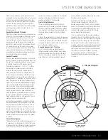
IMPORTANT NOTE:
The AVR 340’s remote may
be programmed to control up to eight devices,
including the AVR 340. Before using the remote, it is
important to remember to press the
Input Selector
Button
e
that corresponds to the unit you wish
to operate.
The AVR 340’s remote is shipped from the factory to
operate the AVR 340 and most Harman Kardon CD or
DVD players and cassette decks. The remote is also
capable of operating a wide variety of other products
using the control codes that are part of the remote.
Before using the remote with other products, follow the
instructions on page 48 to program the proper codes
for the products in your system.
It is also important to remember that many of the but-
tons on the remote take on different functions, depend-
ing on the product selected using the Device Control
Selectors. The descriptions shown here primarily detail
the functions of the remote when it is used to operate
the AVR 340. (See pages 49–52 for information about
alternate functions for the remote’s buttons.)
a
Power Off Button:
Press this button to place the
AVR 340 or a selected device in the Standby mode.
b
IR Transmitter Window:
Point this window
towards the AVR 340 when pressing buttons on the
remote to make certain that infrared commands are
properly received.
c
Program Indicator:
This three-color indicator is
used to guide you through the process of program-
ming the remote. (See page 48 for information on
programming the remote.)
d
Power On Button:
Press this button to turn on
the power to a device selected by pressing one of the
Input Selectors
e
.
e
Input Selectors:
Pressing one of these buttons
will perform three actions at the same time. First, if the
AVR 340 is not turned on, this will power up the unit.
Next, it will select the source shown on the button as
the input to the AVR 340. Finally, it will change the
remote control so that it controls the device selected.
After pressing one of these buttons you must press
the
AVR Selector Button
f
again to operate the
AVR 340’s functions with the remote.
f
AVR Selector:
Pressing this button will switch the
remote so that it will operate the AVR 340’s functions.
If the AVR 340 is in the Standby mode, it will also turn
the AVR 340 on.
g
AM/FM Tuner Select:
Press this button to select
the AVR 340’s tuner as the listening choice. Pressing
this button when the tuner is already in use will select
between the AM and FM bands.
h
Dim Button:
Press this button to activate the
Dimmer function, which reduces the brightness of the
front panel display, or turns it off entirely. The first press
of the button shows the default state, which is full bright-
ness by indicating
VFD FULL
in the
Lower
Display Line
ı
. Press the button again within five
seconds to reduce the brightness by 50%, as indicated
by
VFD HALF
showing in the
Lower Display Line
ı
. Press the button again within five seconds and the
main display will go completely dark. Note that this set-
ting is temporary, in that regardless of any changes, the
display will always return to full brightness when the AVR
is turned on. In addition, the
Power Indicator
2
will
always remain at full brightness regardless of the setting.
This is to remind you that the AVR is still turned on.
i
Test Button:
Press this button to begin the
sequence used to calibrate the AVR 340’s output levels.
(See pages 25, 31 and 42 for more information on
calibrating the AVR 340.)
j
Sleep Button:
Press this button to place the unit
in the Sleep mode. After the time shown in the display,
the AVR 340 will automatically go into the Standby
mode. Each press of the button changes the time until
turn-off in the following order:
See page 34 for more information on the Sleep
Function. This button is also used to change channels
on your TV when the TV is selected.
k
DSP Surround Mode Selector:
Press this but-
ton to cycle through the DSP, VMAx and Stereo sur-
round modes such as Hall, Theater, VMAx Near and
Far, and Surround Off. This button is also used to tune
channels when the TV is selected using the device
Input Selector
e
.
l
Night Mode:
Press this button to activate the
Night mode. This mode is available in specially
encoded digital sources, and it preserves dialogue
(center channel) intelligibility at low volume levels.
m
Channel Select Button:
This button is used to
start the process of setting the AVR 340’s output levels
to an external source. Once this button is pressed, use
the
⁄
/
¤
Buttons
n
to select the channel being
adjusted, then press the
Set Button
p
, followed by
the
⁄
/
¤
Buttons
n
again, to change the level set-
ting. (See pages 31 and 42 for more information.)
However, Harman Kardon recommends that you first
perform the EzSet/EQ procedure, as described on
pages 25 to 27.
n
⁄
/
¤
Buttons:
These multipurpose buttons are
used to change or scroll through items in the on-
screen menus, make configuration settings such as
digital inputs or delay timing, or to select surround
modes. When changing a setting, first press the button
for the function or setting to be changed (e.g., press
the
DSP Surround Mode Selector
k
to select a
sound field mode or the
Digital Select Button
q
to change a digital input) and then press one of these
buttons to scroll through the list of options or to
increase or decrease a setting. The sections in this
manual describing the individual features and functions
contain specific information on using these buttons
for each application.
o
‹
/
›
Buttons:
These buttons are used to change
the menu selection or setting during some of the setup
procedures for the AVR 340.
p
Set Button:
This button is used to enter settings
into the AVR 340’s memory. It is also used in the
setup procedures for delay time, speaker configuration
and channel output level adjustment.
q
Digital Select:
Press this button to assign one
of the digital inputs
*(
fif
to a source. (See
pages 22 and 38 for more information on selecting
digital inputs.)
r
Numeric Keys:
These buttons serve as a 10-
button numeric keypad to enter tuner preset positions.
They are also used to select channel numbers when
TV, Cable or SAT has been selected on the remote, or
to select track numbers on a CD, DVD or LD player,
depending on how the remote has been programmed.
I
Tuner Mode:
Press this button when the tuner
is in use to select between automatic tuning and
manual tuning. When the button is pressed so that
MANUAL
appears in the
Lower Display Line
ı
,
pressing the
Tuning Buttons
9u
will move the
frequency up or down in single-step increments.
When the FM band is in use, pressing this button when
a station’s signal is weak will change to monaural
reception. (See page 41 for more information.)
J
Direct Button:
Press this button when the tuner
is in use to start the sequence for direct entry of a
station’s frequency. After pressing the button, simply
press the proper
Numeric Keys
r
to select a sta-
tion. (See page 41 for more information on the tuner.)
AVR 340 OM 3/22/06 9:09 AM Page 12
Summary of Contents for AVR 340
Page 67: ......


