


SYSTEM CONFIGURATION
SYSTEM CONFIGURATION
26
SYSTEM CONFIGURATION
26
SYSTEM CONFIGURATION
Automated Speaker Setup Using
EzSet/EQ
The AVR 340 is one of the first receivers in its class to
offer automated speaker setup and system calibration.
This process greatly simplifies the installation of your
new receiver by using a series of test signals and
the power of an advanced digital signal processing
system to eliminate the need for manual adjustment
of speaker “size”, crossover, delay and output level
settings, while adding the power of a multi-band para-
metric equalizer to smooth out any peculiarities in fre-
quency response that may result from the characteris-
tics of the listening room. With EzSet/EQ, your new
receiver even alerts you to errors in speaker connec-
tions that prevent a speaker from functioning.
EzSet/EQ calibrates your system in a fraction of the
time it would take to enter the settings manually, and
with results that rival those achieved with expensive
test equipment and time-consuming procedures. The
end result is that your new receiver is able to deliver
the best possible sound, no matter what type of
speakers you have or what the dimensions of your
listening room are.
We recommend that you take advantage of the preci-
sion of EzSet/EQ to calibrate your system, but you
may also make any of the configuration settings man-
ually, or trim the settings provided by EzSet/EQ by fol-
lowing the instructions on pages 27–33.
If you wish to configure your AVR manually (or if
your EzSet/EQ microphone is unavailable), follow
the instructions on pages 27–33.
Step 1:
EzSet/EQ requires that your listening room
have as little background noise as possible to avoid
interfering with the measurement of tones produced
by your AVR during the setup procedure. Turn off all
loud fans, air conditioners and other equipment, and
try to avoid making any noise during the process.
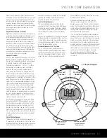
Step 2:
The EzSet/EQ microphone should be placed
in your usual listening position or, in a large seating
area, the center of the room, at the listeners’ ear level.
You may find it convenient to use a camera tripod for
stable placement of the EzSet/EQ microphone at the
correct height. The microphone includes a threaded
insert on the bottom for tripod mounting.
Step 3:
Plug the EzSet/EQ microphone into the
AVR 340’s
Headphone Jack
4
, making certain
that the mini-plug to 1/4" phone plug adaptor sup-
plied with the microphone is firmly connected. The
microphone cable is approximately 20 feet long,
which should accommodate most listening room situa-
tions. If required, you may use an optional extension
cable, available at most electronics stores, for use in
larger rooms. However, we recommend that you avoid
using extension cords for the microphone cable, as
they may adversely affect the test results.
Step 4:
Once the microphone is properly positioned
and plugged in, proceed to the EzSet/EQ menus by
first pressing the
OSD Button
v
to bring the
MASTER MENU
to the screen. Next, press the
⁄
/
¤
Buttons
n
to move the on-screen cursor
to the
EzSet/EQ
menu line. Press the
Set
Button
p
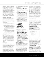
to move to the next screen (Figure 7).
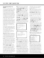
Step 5:
The first screen of the EzSet/EQ system will
now appear to remind you to plug in the microphone.
If you have not already done so, plug the microphone
into the
Headphone Jack
4
as described in Steps
2 and 3. When you are ready to proceed, make cer-
tain that the cursor is pointing to
YES
and press the
Set Button
p
. If you do not wish to continue with
the EzSet/EQ process, press the
‹
/
›
Buttons
o
so that the cursor points to
NO
, and then press the
Set Button
p
to return to the
MASTER
MENU
. Note that if you attempt to move to the next
menu without plugging in the microphone, a reminder
message will flash at the bottom of the screen.
Figure 7
Figure 8
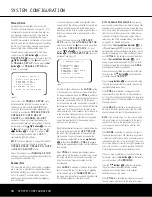
Step 6:
After entering
YES
to start the EzSet/EQ
system, you will next see a warning message (Fig. 8),
and the screen will change to the main EzSet/EQ
menu. The
WARNING
screen is a reminder that in
order for the system to perform accurate measure-
ments, it is important that the listening room be as
quiet as possible. After 5 seconds, the screen will
again display the main EzSet/EQ menu (Figure 9).
IMPORTANT NOTE:
Anyone with hearing that is sen-
sitive to loud noises should leave the room at this
point, or use ear protection sufficient to reduce the
noise level. Inexpensive foam-style ear plugs, available
at most drug stores, may be used to reduce the sound
level to a tolerable level. If you are uncomfortable with,
or cannot tolerate, loud sounds and do not use some
sort of ear protection, we strongly recommend that
you leave the room and ask someone else to run the
EzSet/EQ process, or that you do not use EzSet/EQ
and enter the configuration settings manually, as
described on pages 27–33.
Step 7:
While the main EzSet/EQ menu is visible, you
may start and stop the calibration process, or monitor
the progress of the measurements and view the
results. When the screen first appears, you will see
MEASUREMENT: STOP
on the first line
of the menu list. To start the EzSet/EQ test process,
you must first tell the system how many speakers
are in your system. To do that, choose one of these
two options:
• If your system includes a full complement of seven
main speakers (front left, center, front right, sur-
round right, surround back right, surround back left,
surround left) and a subwoofer, press the
‹
/
›
Buttons
o
so that
7.1
appears to the right
of
MEASUREMENT
, and then press the
Set Button
p
to start EzSet/EQ.
• If your system includes a traditional surround speaker
complement of five main speakers (front left, center,
front right, surround right, surround left) and a sub-
woofer, press the
‹
/
›
Buttons
o
so that
5.1
appears to the right of
MEASUREMENT
, and
then press the
Set Button
p
to start EzSet/EQ.
To stop the calibration process at any time, press
the
⁄
/
¤
Buttons
n
to move the on-screen
cursor to the
MEASUREMENT
line; press the
‹
/
›
Buttons
o
so that
STOP
appears and
then press the
Set Button
p
.
NOTE:
Using EzSet/EQ is not recommended if your
system consists of fewer than six speakers. For smaller
systems, configure your receiver using the manual
setup section on pages 27–33.
Figure 9
Step 8:
Once EzSet/EQ has been started, you will
hear test signals circulate among all of the speakers
as the system sets the master volume level, checks
for the presence of speakers, sets the distance meas-
urement and calculates delay time settings, sets the
output level for each speaker, sets the speaker “size”,
and sets the speaker crossover point, and automati-
cally equalizes the frequency response to eliminate any
artifacts or reverberation that may occur due to the
specific room characteristics, such as alcoves and
doorways. During the measurement and calibration
process, you may observe the progress of the testing
* EzSet/EQ *
MEASUREMENT : STOP
SETTING LEVEL
SPEAKER CHECK : - - - -
SPEAKER DELAY : - - - -
SPEAKER LEVEL : - - - -
SPEAKER SIZE : - - - -
SPEAKER X-OVER: - - - -
SAVE SETTINGS : - - - -
BACK TO MASTER MENU
* EzSet/EQ *
WARNING
During measurements
please maintain silence.
Loud test signal bursts
will be heard.
* EzSet/EQ *
Place Microphone at
listening position and
plug into Headphone Jack
Do you want to start
EzSet/EQ?
YES NO
AVR 340 OM 3/22/06 9:09 AM Page 26
Summary of Contents for AVR 340
Page 67: ......


