


SYSTEM CONFIGURATION 23
SYSTEM CONFIGURATION
SYSTEM CONFIGURATION 23
SYSTEM CONFIGURATION
to change these defaults, press the
¤
Button
n
to go to the next setting.
To change the Component Video assignment, first
make certain that the cursor is pointing to the
COMPONENT IN
line on the menu screen;
then press the
‹
/
›
Buttons
o
until you see the
desired input. When the desired component video
input has been selected, press the
¤
Button
n
to go to the next setting.
If you wish to associate one of the digital inputs with
the selected input source, press the
¤
Button
n
on the remote while the
INPUT SETUP
menu
(Figure 2) is on the screen, and the on-screen cursor
will drop down to the
DIGITAL IN
line. Press
the
‹
/
›
Buttons
o
until the name of the desired
digital input appears. To return to the analog input,
press the buttons until the word
ANALOG
appears.
When the correct digital input jack appears, press the
¤
Button
n
once so that the
›
cursor appears
next to
BACK TO MASTER MENU
, and
press the
Set Button
p
.
To change the digital input at any time using the dis-
crete function buttons and the semi-OSD system,
press the
Digital Select Button
q
on the remote.
Within five seconds, make your input selection using
the
⁄
/
¤
Buttons
n
until the desired digital or
analog input is shown in the
Upper Display Line
P
and in the lower line of the on-screen display. Press
the
Set Button
p
to enter the new digital input
assignment.
Some digital video input sources (such as a cable box
or HDTV set-top) may change between analog and
digital outputs, depending on which channel is in use.
The AVR 340’s Auto Polling feature allows you to
avoid losing the audio feed when this happens by
automatically searching both analog and digital con-
nections for a signal. Digital audio is the default, and
the unit will automatically switch to analog audio if the
digital audio stream stops.
In cases where only a digital source is used, such as
for a DVD player, you may wish to disable the Auto
Polling feature to prevent the AVR from trying to “find”
an analog source when the digital source is paused.
To turn Auto Polling off for any input, first make certain
that the
›
cursor is pointing to the
AUTO POLL
line on the menu screen. Next, press the
‹
/
›
Buttons
o
so that
OFF
appears. To restore
the Auto Polling feature, repeat the procedure at
any time so that
ON
appears.
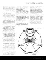
When DMP
has been selected as the source
input, an additional line will appear in this menu that
lets you select whether you wish to allow your iPod to
continue charging while docked in
when the
AVR 340 is turned off and placed in Standby mode.
To make your selection, press the
⁄
/
¤
Buttons
n
until the
›
cursor is next to the line reading
RECHARGE IN ST-BY
. Press the
‹
/
›
Buttons
o
until the word
YES
appears if you
wish charging to continue, and the blue lighting on
The Bridge will remain lit when the AVR 340 is in
Standby mode to indicate that charging is taking
place. The default setting is
NO
, in which the docked
iPod will not continue to charge when the AVR 340
is turned off, even though
remains connected
to the AVR.
When all needed adjustments have been made, press
the
¤
Button
n
until the
›
cursor is next to
BACK TO MASTER MENU
to continue with
the system configuration.
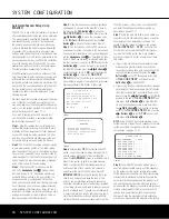
Audio Setup
This menu allows you to configure the tone controls. If
you do not wish to change those settings at this time,
proceed to the next menu screen. However, to make
configuration changes to those parameters, make cer-
tain that the
MASTER MENU
(Figure 1) is on
screen with the
›
cursor pointing to the
AUDIO
SETUP
line, and press the
Set Button
p
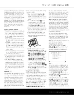
. The
AUDIO SETUP
menu (Figure 3) will appear.
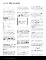
Figure 3
The first line controls whether or not the bass/treble
tone controls are in the signal path. The normal default
is for them to be in-line, but if you wish to remove
them from the circuit for “flat” response, first make
certain that the
›
cursor is pointing to the
TONE
line on the menu and press the
‹
/
›
Buttons
o
so that
OUT
appears.
If you wish to leave the tone controls in the signal
path, make sure that
IN
appears on the
TONE
line, using the
‹
/
›
Buttons
o
to adjust this set-
ting if necessary. The amount of boost or cut for bass
and treble may be adjusted by up to ±10dB, in 2dB
increments, by pressing the
⁄
/
¤
Buttons
n
so
that the
›
cursor is next to
BASS
or
TREBLE
depending on which setting you wish to adjust. Next,
press the
‹
/
›
Buttons
o
until the desired setting
is shown.
When all desired changes have been made on this
menu, press the
¤
Button
n
so that the
›
cur-
sor is next to the
BACK TO MASTER MENU
line; press the
Set Button
p
.
Surround Setup
The next step is to set the surround mode you wish
to use with the input that was previously selected in
the
INPUT SETUP
menu. Since surround
modes are a matter of personal taste, feel free to
select any mode you wish – you may change it later.
However, to make it easier to establish the initial
parameters for the AVR 340, it is best to select Dolby
Pro Logic II or Logic 7 for most analog inputs. In the
case of inputs such as a CD Player, Tape Deck or
Tuner, you may wish to set the mode to Stereo
(“Surround Off”) as they are not typically used with
multichannel program material, and it is unlikely that
surround-encoded material will be used. Alternatively,
the Logic 7 Music mode is a good choice for stereo-
only source material. See pages 35–40 for more
information on available surround modes.
When selecting surround modes for digital program
material, the AVR 340 will always examine the data
stream and automatically select Dolby Digital or DTS
as applicable.
IMPORTANT NOTES:
• You will not be able to access any of the Dolby
Digital or DTS Digital modes unless a source signal
in that format is present. Thus, in order to make
adjustments to the output levels and delay settings
(if available) for these modes, you will need to play
a source in that format, such as a DVD.
• You will not be able to access any of the 6.1- or
7.1-channel modes; such as Dolby Digital EX, DTS
Neo:6 (6CH), 7-channel Stereo and Logic 7/7.1;
unless the AVR 340 has been configured for 6.1-/
7.1-channel operation by setting the surround back
speaker channels to
SMALL
or
LARGE
using
the
SPEAKER SIZE
submenu, which is
accessed from the
MANUAL SETUP
sub-
menu. See page 28 for more information. Note that
the AVR 340 is configured for 6.1/7.1 operation by
default.
It is easiest to complete the surround setup using
the full-OSD on-screen menus, although you may also
use the remote control buttons for each mode group
(see pages 12–13). From the
MASTER
MENU
(Figure 1), press the
⁄
/
¤
Buttons
n
until the
›
cursor is next to the
SURROUND SELECT
line. Then press the
Set Button
p
until the
SURROUND SELECT
submenu (Figure 3)
is on the screen.
* AUDIO SETUP *
TONE :IN
BASS :0
TREBLE :0
BACK TO MASTER MENU
The
Bridge
TM
The
Bridge
TM
The
Bridge
TM
AVR 340 OM 3/22/06 9:09 AM Page 23
Summary of Contents for AVR 340
Page 67: ......


