


Manual Setup
Harman Kardon recommends that you use the
EzSet/EQ procedure described on pages 25–27 to
configure your receiver for operation. However, you
may manually configure your AVR, if you have run
EzSet/EQ but wish to make adjustments, if your
EzSet/EQ microphone is not available, or if you simply
prefer to make your adjustments manually. In addition,
the A/V Sync Delay setting may only be performed
manually (see Delay Settings section, page 31).
To begin manual setup using the full-OSD menu
system, press the
OSD Button
v
so that the
MASTER MENU
appears on screen. Press the
⁄
/
¤
Buttons
n
until the
›
cursor points to
the
MANUAL SETUP
line, and press the
Set
Button
p
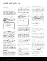
. The
MANUAL SETUP
menu
(Figure 11) will appear.
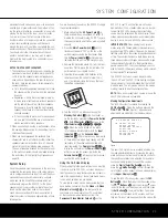
Figure 11
The first line of the
MANUAL SETUP
menu
indicates whether EzSet/EQ has been run and its
settings saved. If this line indicates
YES
, then
you will be able to see the settings determined by
EzSet/EQ as you view the
SPEAKER SIZE
,
SPEAKER X-OVER
,
DELAY
ADJUST
and
CHANNEL ADJUST
submenus. If you wish to reset the speaker size,
crossover, output level and delay settings to their fac-
tory defaults, use the
⁄
/
¤
Buttons
n
to move
the
›
cursor to point to this line, and then use the
‹
/
›
Buttons
o
to change this setting to
NO
.
You may change this setting back to
YES
to
reactivate the EzSet/EQ settings.
NOTE:
If you have forgotten to unplug the EzSet/EQ
microphone, you will not be able to access the
SPEAKER SIZE
,
SPEAKER X-OVER
and
DELAY ADJUST
menus.
Adjust the submenus in the
MANUAL SETUP
submenu in order, as some settings require that previ-
ous settings be established first.
Speaker Size
This menu tells the AVR 340 which type of speakers
are in use. This is important as it adjusts the settings
that decide whether your system will use the “5-chan-
nel” or “6-channel/7-channel” modes, as well as
determining which speakers receive low-frequency
(bass) information.
If you have already completed an automated setup
using EzSet/EQ the settings calculated during that pro-
cedure will already appear. No further adjustment is
required unless you wish to change a specific item to
reflect your personal taste or a nonstandard system
configuration.
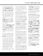
You will first need to access the
SPEAKER
SIZE
submenu. With the
MANUAL SETUP
submenu on screen, the
›
cursor should be pointing
to the first line,
SPEAKER SIZE
. If it is not,
use the
¤
Button
n
until it is, then press the
Set
Button
p
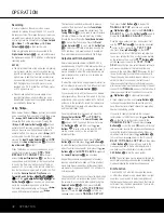
. The
SPEAKER SIZE
submenu
will appear (see Figure 12).
Figure 12
For each of these settings, use the
LARGE
setting
if the speakers for a particular position are traditional
full-range loudspeakers. Use the
SMALL
setting for
smaller, frequency-limited satellite speakers that do not
reproduce sounds below 200Hz. Note that when
“small” speakers are used, a subwoofer is required to
reproduce low-frequency sounds. Remember that the
“large” and “small” descriptions do not refer to the
actual physical size of the speakers, but to their ability
to reproduce low-frequency sounds. If you are in
doubt as to which category describes your speakers,
consult the specifications in the speakers’ owner’s
manual, or ask your dealer.
Begin the speaker setup process by making certain that
the cursor is pointing toward the
LEFT
/
RIGHT
line, which sets the configuration for the front left and
right speakers. If you wish to make a change to the
front speakers’ configuration, press the
‹
/
›
Buttons
o
so that either
LARGE
or
SMALL
appears,
matching the appropriate description from the definitions
shown above.
When
SMALL
is selected, low-frequency sounds
will be sent only to the subwoofer output. If you choose
this option and there is no subwoofer connected, you
will not hear any low-frequency sounds from the
front channels.
When
LARGE
is selected, a full-range output will be
sent to the front left and front right outputs. Depending
on the choice made in the
SUBWOOFER
line in
this menu, bass information may also be directed to the
front left/right speakers, a subwoofer or both.
NOTE ON ANALOG BYPASS MODE:
If an analog
audio source is selected and you have full-range front
speakers, you may select an analog bypass two-chan-
nel mode in which the analog signal is routed directly
from the input to the volume control, without being
digitized or processed. The analog bypass mode is
selected as one of the surround modes. See the note
on page 25 for detailed instructions.
When the DSP
Surround Mode Indicator
ˆ
is lit
in
Surround Off
mode, the input signal is
being digitized and bass management settings will be
applied. For example, if you have set the front speak-
ers to
SMALL
, this setting will be selected. When
the DSP
Surround Mode Indicator
ˆ
is not lit,
analog bypass mode is engaged. The AVR will auto-
matically configure the front speakers as
LARGE
,
overriding your manual configuration.
When you have completed your selection for the front
channel, press the
¤
Button
n
on the remote to
move the cursor to
CENTER
.
Press the
‹
/
›
Buttons
o
on the remote to select
the option that best describes your system, based on the
speaker definitions shown below.
When
SMALL
is selected, low-frequency center
channel sounds will be sent only to the subwoofer out-
put. If you choose this option and there is no subwoofer
connected, you will not hear low-frequency sounds from
the center channel.
When
LARGE
is selected, a full-range output will
be sent to the center speaker output, and NO center
channel signal will be sent to the subwoofer output.
NOTE:
If you choose Logic 7 as the surround mode
the “large” option will not be available for the center
speaker. This is due to the requirements of Logic 7
processing, and does not indicate a problem with
your receiver.
When
NONE
is selected, no signals will be sent to
the center channel output. The receiver will operate in
a “phantom” center channel mode and center channel
information will be sent to the left and right front chan-
nel outputs. When only front left and right speakers are
used, with no center or surround speakers, VMAx and
Dolby Virtual Speaker are good alternative modes.
When you have completed your selection for the cen-
ter channel, press the
¤
Button
n
on the remote
to move the cursor to
SURROUND
.
Press the
‹
/
›
Buttons
o
on the remote to select
the option that best describes the side surround
speakers in your system based on the speaker
definitions shown on this page.
When
SMALL
is selected, low-frequency surround
channel sounds will be sent to the subwoofer output
* SPEAKER SIZE *
LEFT/RIGHT:SMALL
CENTER :SMALL
SURROUND :SMALL
SURR BACK :SMALL MAIN
SUBWOOFER :SUB
BASS MGR :GLOBAL
BACK TO MANUAL SETUP
* MANUAL SETUP *
EzSet ACTIVATE:NO
SPEAKER SIZE
SPEAKER X-OVER
DELAY ADJUST
CHANNEL ADJUST
BACK TO MASTER MENU
28
SYSTEM CONFIGURATION
28
SYSTEM CONFIGURATION
SYSTEM CONFIGURATION
SYSTEM CONFIGURATION
AVR 340 OM 3/22/06 9:09 AM Page 28
Summary of Contents for AVR 340
Page 67: ......


