ENGLISH
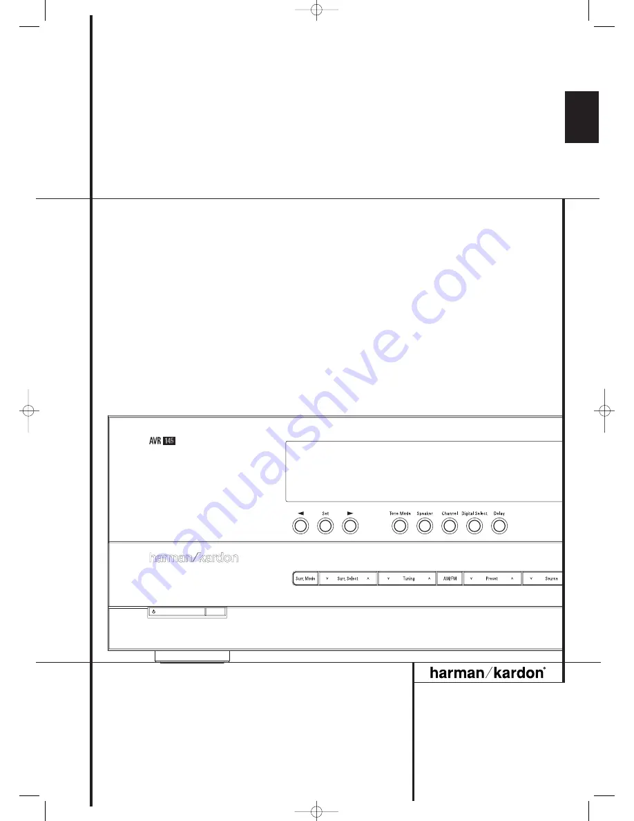
AVR 145
Audio/VideoReceiver
OWNER’S MANUAL
30935_AVR145_ENG 01/12/06 9:53 Side 1
Page 1: ...ENGLISH AVR 145 Audio VideoReceiver OWNER S MANUAL 30935_AVR145_ENG 01 12 06 9 53 Side 1 ...
Page 2: ...mming the Remote 41 Programming the Remote with Codes Table of Contents Typographical Conventions In order to help you use this manual with the remote control front panel controls and rear panel con nections certain conventions have been used EXAMPLE bold type indicates a specific remote control or front panel button or rear panel connection jack EXAMPLE OCR type indicates a message that is visibl...
Page 3: ...ltimate in flexibility the AVR features connections for four video devices all with both composite and S Video inputs Two additional audio inputs are available and a total of six digi tal inputs and two outputs make the AVR 145 capable of handling all the latest digital audio sources Coax and optical digital outputs are available for direct connection to digital recorders A video recording output ...
Page 4: ...a shelf be certain that the shelf and any mounting hardware can support the weight of the product Make certain that proper space is provided both above and below the unit for ventilation If this product will be installed in a cabinet or other enclosed area make certain that there is sufficient air movement within the cabinet Under some circumstances a fan may be required Do not place the unit dire...
Page 5: ...evel group of surround modes Each press of the button will select a major mode grouping in the following order Dolby Modes DTS Digital Modes DSP Modes Stereo Modes Logic 7 Modes Once the button is pressed so that the name of the desired surround mode group appears in the Main Information Display Ò press the Surround Mode Selector 9 to cycle through the individual modes available For example press ...
Page 6: ...e L and R will light indicating a stereo input When a digital source is playing the indica tors will light to display the channels begin received at the digital input When the letters flash the digital input has been interrupted See page 34 for more information on the Channel Indicators Input Source Selector Press this button to change the input by scrolling through the list of input sources RDS S...
Page 7: ... antenna is used make connections to the AM and GND terminals in accordance with the instructions supplied with the antenna 1 FM Antenna Connect the supplied indoor or an optional external FM antenna to this terminal 2 Tape Inputs Connect these jacks to the PLAY OUT jacks of an audio recorder 3 Tape Outputs Connect these jacks to the RECORD INPUT jacks of an audio recorder 4 Subwoofer Output Conne...
Page 8: ...o jacks on a VCR or other audio or video source I AC Power Cord Connect the AC plug to an unswitched AC wall output J Video 2 Component Video Inputs Connect the Y Pr Pb component video outputs of an HDTV Set top convertor satellite receiver or other video source device with component video outputs to these jacks K Monitor Component Video Outputs Connect these outputs to the component video inputs ...
Page 9: ...ton Dolby Mode Select Button DTS Digital Mode Selector Logic 7 Mode Select Button Transport Controls EzSet Sensor Microphone Skip Up Down Buttons Stereo Mode Select Button DTS Neo 6 Mode Select Macro Buttons RDS Selector Button Preset Up Down Clear Button Memory Button Delay Prev Ch Button Speaker Select Mute Volume Up Down DMP Selector TV Video Selector Dim Button Tone Mode EzSet SPL Button NOTE ...
Page 10: ... preserves dialog center channel intelligibilty at low vol ume levels See page 20 for more information C Channel Select Button This button is used to start the process of setting the AVR s output levels with an external source Once this button is pressed use the buttons D to select the channel being adjusted then press the Set button F followed by the buttons D again to change the level setting Se...
Page 11: ...t the right side of the Main Information Display Ò you then have five seconds to enter a preset memory location using the Numeric Keys H See page 40 for more information Delay Prev Ch Press this button to begin the process for setting the delay times used by the AVR when processing surround sound After pressing this button the delay times are entered by pressing the Set button F and then using the...
Page 12: ...le are available and the choice of cable may be influen ced by the distance between your speakers and the receiver the type of speakers you use personal preferences and other factors Your dealer or installer is a valuable resource to consult in selecting the proper cable Regardless of the brand of cable selected we recommend that you use a cable constructed of fine multistrand copper with an area ...
Page 13: ...rom Scart to 2 RCA 1 S Video plugs see fig 4 S Video devices HiFi VCRs need an adapter from Scart to 6 RCA plugs see fig 2 normal video or from Scart to 4 Audio 2S Video jacks see fig 5 S Video VCR Read carefully the instruction attached to the adapter to find which of the six plugs is used for the record signal to the VCR connect with the AVR s Out jacks and for the playback signal from the VCR c...
Page 14: ...deo source is started And with DVD players the signals automatically turning the TV to 4 3 16 9 format with 16 9 TVs or with 4 3 TVs with selectable 16 9 format and turning the RGB video decoder of the TV on or off depending on the DVD player s setting With any adapter cable these control signals will be lost and the appropriate setting of the TV must be made manually Note for RGB signal with SCAR...
Page 15: ... that have no power switch or a mechanical power switch that may be left in the ON position NOTE Many audio and video products go into a Standby mode when they are used with switched outlets and cannot be fully turned on using the outlet alone without a remote control command The AVR draws significantly more current than other household devices such as computers that use removable power cords For ...
Page 16: ...y find that imaging is improved by moving the front left and front right speakers slightly for ward of the center channel speaker If possible adjust all front loudspeakers so that they are aimed at ear height when you are seated in the listening position Using these guidelines you ll find that it takes some experimentation to find the correct loca tion for the front speakers in your particular ins...
Page 17: ...modes Semi OSD and Full OSD When making configuration adjustments it is recommended that the Full OSD mode be used This will place a complete status report or option listing on the screen making it easier to view the available options and make the settings on the screen The Semi OSD mode uses one line displays only Note that when the full OSD system is in use the menu selections are not shown in t...
Page 18: ...reverse list of the alphabet in lower case letters Press the button either way until the first letter of the desired name appears If you wish to enter a blank space as the first character press the Navigation Button When the desired character appears press the Navigation Button and repeat the process for the next letter and continue until the desired name is entered up to a maximum of fourteen cha...
Page 19: ... setting is shown When all needed adjustments have been made press the Button D until the cursor is next to BACK TO MASTER MENU to contin ue with the system configuration Surround Setup The next step for that input is to set the surround mode you wish to use with that input Since surround modes are a matter of personal taste feel free to select any mode you wish you may change it later The Surroun...
Page 20: ... the 5 1 configuration is in use the AVR will automatically select the 5 1 version of DTS processing when a DTS data stream is received When a DTS 96 24 signal is detected the AVR 145 defaults to the DTS surround mode but reproduces the higher resolution materials that are present due to the higher sampling rate auto matically See page 28 and 29 for a complete explanation of the DTS modes On the L...
Page 21: ... configured for 5 1 operation with standard speakers Note that all speakers currently in use always are indicated by the Speaker Channel Indicators in the front panel display Once the correct channel configuration button has been pressed the test noise will be heard from the front left speaker 6 At this point EzSet will take over adjusting the output level of each channel so that when the process ...
Page 22: ...rce selected and to use them with any movie input source With the currently selected input all speaker settings will be copied to all other surround modes as far as speakers are used with them and need not be repeated when another sur round mode is selected with that input It is easiest to enter the proper settings for the speaker setup through the SPEAKER SIZE menu Figure 9 So press the OSD Butto...
Page 23: ... is selected no signals will be sent to the center channel output The receiver will operate in a phantom center channel mode Center channel information will be sent to the left and right front channel outputs and the cen ter channel bass will be sent to the subwoofer output when L R LFE is selected in the SUBWOOFER line in this menu see below This mode is needed if no Center speaker is used Note t...
Page 24: ...er the LFE option line enables you to select a setting for the low pass filter that is part of the sub woofer feed from the LFE channel The settings available are the same as those tied to any one of the four available speaker positions on this submenu We recommend that you use the fre quency that is just slightly higher than the upper capability limit of your subwoofer as shown in the sub s Owner...
Page 25: ...tances the Logic 7 modes allow access to the settings for all channels without requiring that you play a source To start with the delay settings at first select the DELAY ADJUST MENU Figure 11 If the system is not already at that point press the OSD button L to bring up the master menu Press the Button D three times or until the on screen cursor is pointing at the MANUAL SETUP line Press the Set B...
Page 26: ...ective with all inputs associated with the same surround mode Before beginning the output level adjustment process make certain that all speaker connec tions have been properly made The system volume should be turned down at first For the easiest set up follow these steps while seated in the listening position that will be used most often 1 Make certain that all speaker positions have been properl...
Page 27: ...bwoofer output level is not adjustable using the test tone To change the subwoofer level follow the steps for Output Level Trim Adjustment on page 36 When all channels have an equal volume level the adjustment is complete Now turn the Volume down to about 40dB otherwise the listening level may be too high as soon as the source s music starts to play To exit this menu press the buttons D until the ...
Page 28: ...o mode creating separate rear left and rear right signals in any case The Pro Logic II mode creates compelling five channel surround sound from conventional stereo recordings Game mode ensures that special effects are routed to the surround channels while delivering their full impact using the subwoofer thus fully immersing the game player in the universe of the video game Logic 7 Cinema Exclusive...
Page 29: ... Wide Mode provides a wider more spacious front image when the two speakers areclose together THEATER The THEATER mode creates a sound field that resembles the acoustic feeling of a standard live performance theater with stereo and even pure mono sources HALL 1 The two Hall modes create sound fields that resemble a small HALL1 or HALL 2 medium sized HALL 2 concert hall with stereo and even pure mo...
Page 30: ... 5 to have the remote control the AVR functions The input source may also be changed by pressing the front panel Input Source Selector button Each press of the button will move the input selection through the list of available inputs As the input is changed the AVR will auto matically switch to the digital input if selected surround mode and speaker configuration that were entered during the confi...
Page 31: ...ey are broadcast via conventional TV stations cable pay TV and satellite transmission In addition a growing number of made for television programs sports broadcasts radio dramas and music CDs are also recorded in surround sound You may view a list of these programs at the Dolby Laboratories Web site at www dolby com Even when a program is not listed as carrying intentional surround information you...
Page 32: ...onnected a digital source to the AVR Connect the digital outputs from DVD players HDTV receivers satellite systems or CD players to the Optical or Coaxial inputs on the rear or front panel RN Ó In order to provide a backup signal and a source for analog stereo recording the analog outputs provided on digital source equipment should also be connected to their appropriate inputs on the AVR rear pane...
Page 33: ...en a Dolby Digital signal with a 3 1 0 or 2 0 0 signal is detected you may select any of the Dolby sur round modes Surround Mode Post Processing Thanks to the power of the AVR 145 s DSP processor a variety of surround mode options are available for most digital signals to deliver either the native information or to produce an enhanced sound field to match the number of speakers in your system The ...
Page 34: ...features a set of unique channel input indicators that tell you how many channels of digital information are being received and or whether the digital signal is interrupted See Figure These indicators are the L C R LFE SL SR letters that are inside the center boxes of the Speaker Channel Input Indicators in the front panel Main Information Display Ò When a standard analog stereo or matrix surround...
Page 35: ...ne which type of audio has been recorded on the disc The AVR will automatically sense the type of digital surround encoding used indicate it in the Channel Input Indicators and adjust to accommodate it When a Dolby Digital or DTS source is playing you normally may not be able to select some of the analog surround modes such as Dolby Pro Logic II Dolby 3 Stereo Hall Theater 5CH Stereo or Logic 7 ex...
Page 36: ...position use the Buttons E to change the output level Remember when you are using a disc with test signal e g pink noise or an external signal generator as the source the goal is to have the output level at each channel be equal when heard at the listening position with any surround mode selected When your test source is a nor mal disc with music signals you may adjust the level for each channel a...
Page 37: ...ULT VOL SET line Note that this setting may NOT be made with the regular volume controls NOTE Since the setting for the turn on volume cannot be heard while the setting is being made you may wish to determine the setting before making the adjustment To do this listen to any source and adjust the volume to the desired level using the regular volume controls When the desired volume level to be used ...
Page 38: ...ar when Dolby Digital or DTS is present The AVR allows you to set the unit so that it will either respond to the default or switch to your desired mode If you wish to leave the default so that the mode choice encoded in the disc is always used no further action is needed Simply leave the setting at the factory default of ON To set the unit so that it responds to the last sur round mode used when a...
Page 39: ...TUNED will appear in the Main Information Display Ò 4 Stations may also be tuned directly by pressing the Direct button J and then pressing the Numeric Keys H that correspond to the station s frequency Note that for entering numbers higher than 100 you need to enter only the 1 rather than 10 the first 0 will be added automatically The desired station will automatically be tuned after the latest nu...
Page 40: ... NO TIME message after the individual time out In any FM mode the RDS function requires a strong enough signal for proper operation Program Search PTY An important feature of RDS is its capability of encoding broadcasts with Program Type PTY codes that indicate the type of material being broadcast The following list shows the abbreviations used to indicate each PTY along with an explanation of the...
Page 41: ...etup code guide or if not all functions operate properly try programming the remote with the Auto Search Method Note on Using the AVR remote with a Harman Kardon CD Recorder As shipped from the factory the remote is programmed for controlling Harman Kardon CD players It can also control most functions of the Harman Kardon CD Recorders see function list on page 44 45 too after the code 002 is enter...
Page 42: ...nder the Selector will go out and the Program Indicator 2 will turn green and flash three times before it goes out 5 When the Program Indicator 2 goes out the Macro has been erased Programmed Device Functions Once the AVR s remote has been programmed for the codes of other devices press the appropriate Input Selector 4 to change the remote from control over the AVR to the additional product When y...
Page 43: ...eps shown in the example above However press the same Input Selector in Steps 1 and 3 Transport Control Punch Through The AVR s remote may be programmed to operate so that the Transport Control Functions P Play Stop Fast Forward Rewind Pause and Record for a VCR DVD or CD will operate in conjunction with one of the other devices con trolled by the remote For example while using and controlling the...
Page 44: ...Intro Scan 25 Move Adjust Up Up 26 fi Move Adjust Left Left 27 Set Set Enter 28 fl Move Adjust Right Right 29 Move Adjust Down Down 30 Digital Exit Digital Input Select Open Close 31 Delay Prev Ch Delay Adjust Return or Status Open Close 32 1 1 1 1 1 33 2 2 2 2 2 34 3 3 3 3 3 35 4 4 4 4 4 36 5 5 5 5 5 37 6 6 6 6 6 38 7 7 7 7 7 39 8 8 8 8 8 40 Tun M Tuner Mode Chapter or Zoom Repeat 41 9 9 9 9 9 42 0...
Page 45: ...nel Channel Channel Channel 20 OSD OSD Live TV OSD OSD OSD 21 Blank 22 Volume Down Volume Down Volume Down Volume Down Volume Down Volume Down 23 Channel Guide Guide Info Guide Info Guide 24 Speaker Menu Menu Menu Menu Menu Menu Menu 25 Up Up Up Up Up 26 fi Left Left Left Left Left Scroll 27 Set Enter Select Enter Enter Enter Select 28 fl Right Right Right Right Right Scroll 29 Down Down Down Down D...
Page 46: ... CAUSE SOLUTION Unit does not function when Main No AC Power Make certain AC power cord is plugged Power Switch 1 is pushed into a live outlet Check to see if outlet is switch controlled Display lights but no sound Intermittent input connections Make certain that all input and speaker or picture connections are secure Mute is on Press Mute button Volume control is down Turn up volume control No so...
Page 47: ...620kHz Signal to Noise Ratio 45dB Usable Sensitivity Loop 500µV Distortion 1kHz 50 Mod 0 8 Selectivity 10kHz 30dB Video Section Video Format PAL NTSC Input Level Impedance 1Vp p 75 ohms Output Level Impedance 1Vp p 75 ohms Video Frequency Response Composite and S Video 10Hz 8MHz 3dB Video Frequency Response Component 10Hz 100MHz 3dB General Power Requirement AC 220 240V 50Hz Power Consumption 65W ...
Page 48: ...and Analog audio sources Table A2 Speaker Channel Setting Defaults Source DVD Video 1 Video 2 Video 3 The Bridge CD Tape Tuner 6 DMP Channel Bass Manager Global Left Right Speaker Size Small Small Small Small Small Small Small Small Large Center Speaker Size Small Small Small Small Small Small Small Small Large Surround Speaker Size Small Small Small Small Small Small Small Small Large Surround Ba...
Page 49: ...Channel Level Center Channel Level Surround Channel Level Subwoofer Channel Level The 6 Channel Inputs are direct inputs meaning their signals are passed directly to the volume control without any bass management processing Thus the speaker sizes are always full range and it isn t possible to adjust speaker size or crossover Note Channel levels vary by surround mode rather than source input Table ...
Page 50: ... Drive Woodbury New York 11797 www harmankardon com Harman Consumer Group Inc 2 route de Tours 72500 Château du Loir France 2006 Harman Kardon Incorporated Part No OM P N CQX1A1135Z 30935_AVR145_ENG 01 12 06 9 53 Side 50 ...