14
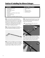
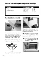
Step 1.
For this assembly, you will be using two 3-3/4”
threaded rods, four clevis, four 4-40 nuts, and a regular and a
reverse metal control horn. Use the 4-40 nuts as locking devices
to keep the clevis from turning. There is also a locking clip that
keeps the clevis from opening. The reverse control horn has an
“R” marked on its base; the standard horn has no marking. For
illustration purposes, we will describe the installation of the
aileron linkage on the right wing panel (bottom).
Step 2.
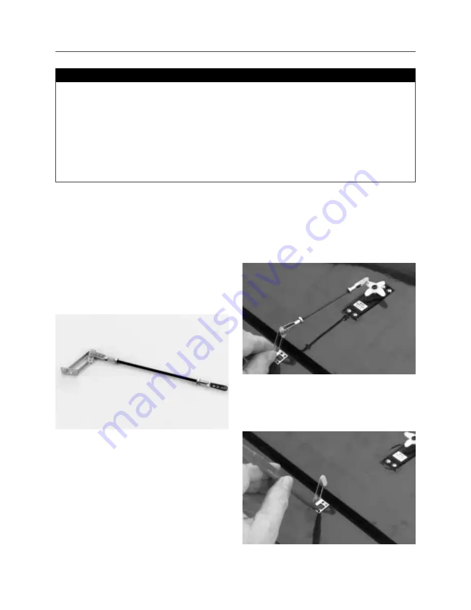
Thread a 4-40 nut and clevis on each end of the
threaded rod. Next locate the standard horn. The link assembly
goes on the 2nd outer hole from the end as shown below.
Step 3.
The metal clevis will attach to the servo arm that points
to the wing tip. If you wish, the other three arms can be trimmed
off. To establish the position of each of the clevis on the threaded
rod, trial fit the horn and linkage to the servo arm. Adjustments
in length are made by screwing one or both clevises in or out.
Step 4.
The servo arm should be positioned so it is pointing to
the wing tip. When installing the control horn, the holes in the
control horns (where the pushrod attaches) should be in line
with the control surface hinge line.
Note:
If using 3-D throws, use a heavy duty servo arm
(JRPA215 for JR Servos.)
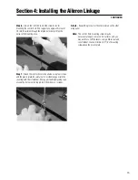
Step 5.
Once you are satisfied with the metal control horn
location (it should be a straight line from the servo arm to the
horn), mark the location of the screw holes with a felt-tipped pen
or pencil. The hinge line and the control rod should be at
90-degree angle to achieve proper mechanical efficiency.
Section 4: Installing the Aileron Linkages
• Wing assembly from Section 2
• Left control horn
• Right (reversed) control horn
• Plastic plate (2)
• Screws (8)
• Short (3-3/4” x 4-40) threaded rod (both ends)(2)
• 4/40 metal clevis (4)
• Locking clips for clevis (4)
• 4/40 nuts (4)
• Heavy duty servo arm (JRPA215) (Optional for 3-D throws)
• Phillips screwdriver
• Drill
• Drill bits: 1/16”, 3/32”
• Felt-tipped pen or pencil
• Moto-tool (optional)
Parts Needed
Tools and Adhesives Needed
Summary of Contents for EDGE 540
Page 52: ...52 ...
Page 53: ...53 Template Cut Out of Cowl Bottom MDS 1 48 ...
Page 54: ...54 ...
Page 55: ...55 ...
Page 56: ... 2000 Horizon Hobby Inc www horizonhobby com ...
Page 57: ...57 ...
Page 58: ...58 ...
Page 59: ...59 ...


