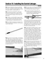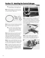
21
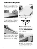
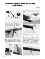
Step 1.
Trial fit the rudder in position on the Vertical Stabilizer
with the hinges in place.
Step 2.
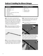
Insert the tail wheel wire into the pivot bushing. With
the pivot bushing resting against the bend in the tail wheel wire,
use a needle-nose pliers to make a 90-degree bend in the
direction shown below in step 3, 1/8” above the top of the pivot
bushing.
Note:
The part of the tail wheel wire that inserts into the
rudder must go into the wood in the rudder. To insure
adequate strength, the bend of the wire must be kept
as low as possible.
Step 3.
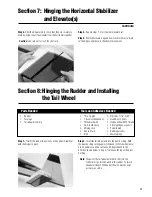
After the hinges are dry, check that they are securely in
place by trying to pull the elevator from the horizontal stabilizer.
Caution:
Use care not to crush the structure.
Step 4.
Repeat steps 1-3 for the other elevator half
Step 5.
Work the elevators up and down several times to “work
in” the hinges and check for freedom of movement.
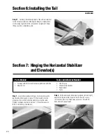
Section 7: Hinging the Horizontal Stabilizer
and Elevator(s)
CONTINUED
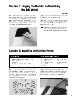
Section 8: Hinging the Rudder and Installing
the Tail Wheel
Fuselage
• Rudder
• Fuselage
• Tail wheel assembly
• Thin CA glue
• CA remover/debonder
• Threadlock Z-42
• 30-minute epoxy
• Mixing stick
• Epoxy brush
• Drill
Parts Needed
Tools and Adhesives Needed
• Drill bits: 1/16”, 3/32”
• Needle-nose pliers
• Hobby knife with #11 blade
• Felt-tipped pen or pencil
• Paper towels
• Rubbing alcohol
• Masking tape
Summary of Contents for EDGE 540
Page 52: ...52 ...
Page 53: ...53 Template Cut Out of Cowl Bottom MDS 1 48 ...
Page 54: ...54 ...
Page 55: ...55 ...
Page 56: ... 2000 Horizon Hobby Inc www horizonhobby com ...
Page 57: ...57 ...
Page 58: ...58 ...
Page 59: ...59 ...

