29
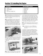
Step 1.
Mix approximately 1 ounce of 30-minute epoxy and an
equal amount of rubbing alcohol. Brush the mixture on the
firewall (and spacer plate) to seal it to make it fuelproof. Allow
the epoxy to cure completely.
Step 2.
Locate the two metal motor mounts and associated
mounting hardware. Note the motor mount screw holes are
shaped like slots in the firewall. This is to allow moving the
motor mounts closer or further apart so engines of different
width crankcases can be mounted. Note also that the motor
mount can only be installed so the engine cylinder faces to the
right side of the aircraft, as seen from the cockpit of the model.
Step 3.
Mount the metal motor mounts on the firewall using the
bolts and washers provided. The blind nuts are installed on the
inside of the fuselage. Do not over tighten the bolts at this time,
as the width of the mount will vary with the size of the engine
crankcase used.
Step 4.
Trial fit your engine on the motor mount by mounting it
loosely to metal motor mount with the 4 bolts, 8 washers, and
4 nuts provided. Adjust the distance between the metal motor
mounts until the engine crankcase fits the motor mount. Check
the metal motor mount position on the firewall, making sure the
mounts are parallel to the bottom of the firewall. Once the proper
distance between the motor mounts is determined and they are
parallel to the bottom of the firewall, tighten the bolts mounting
the motor mount to the firewall securely. A drop of Locktite Z-42
on the bolt threads will help prevent loosening in flight.
Step 5.
Position the engine along the metal motor mount until
you measure 6
1
/
4
” from the firewall to the front end of the prop
drive hub.
Note:
If a shorter engine is used, such as MDS 1.48, the
3/8'' plywood spacer plate must be used behind the
motor mounts.
Once the engine is in proper position, tighten down the motor
mounting bolts securely. Again, a drop of Locktite Z-42 will help
prevent loosening of the bolts in flight. The engine should be
positioned so there is ample clearance in the cowling for the
spinner backplate mounted to the prop drive shaft. If you remove
the engine and reinstall it, make sure the engine is mounted at the
distance previously mentioned. Remember, the key distance is from
the prop drive hub to the firewall.
Section 12: Installing the Engine
• Fuselage
• Metal motor mounts
• Mounting hardware
• Engine
• Spacer Plate (If using MDS 1.48)
• Phillips screwdriver
• 30-minute epoxy
• Rubbing alcohol
• Epoxy brush
• Mixing stick
• Paper towel
• Locktite
®
Z-42
Parts Needed
Tools and Adhesives Needed
Summary of Contents for EDGE 540
Page 52: ...52 ...
Page 53: ...53 Template Cut Out of Cowl Bottom MDS 1 48 ...
Page 54: ...54 ...
Page 55: ...55 ...
Page 56: ... 2000 Horizon Hobby Inc www horizonhobby com ...
Page 57: ...57 ...
Page 58: ...58 ...
Page 59: ...59 ...

