10
Hangar 9 Christen Eagle II 90 ARF
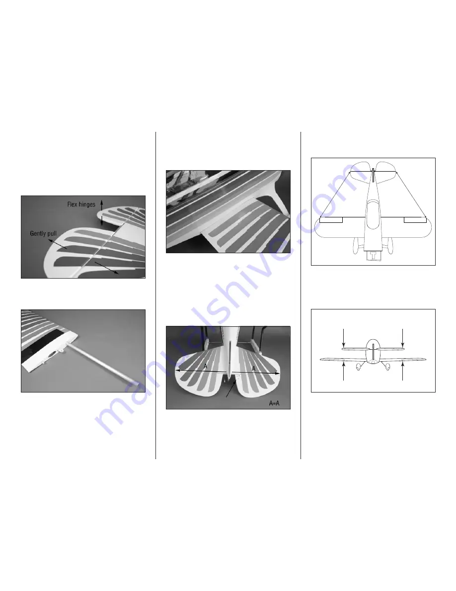
7. Remove the T-pins from the hinges and make sure
the gap between the elevators and stabilizer are as small as
possible. Saturate the top and bottom of each hinge using
thin CA. Allow the CA to cure before proceeding. Check
that the hinges are secure by gently pulling on the control
surface. If not, apply thin CA to any hinges that are not glued
and recheck. Move the control surface through its range of
motion several times to break in the hinges. This will reduce
the initial load on the servo during your first flights.
8. Slide the 12mm x 420mm aluminum tube into the
bottom wing panel. The tube socket has a cap on it, so do
not force the tube in any farther than it will easily slide.
9. Slide the wing into position on the fuselage. Make sure
the wing is tight against the fuselage. Slide the remaining
wing panel into position tightly against the fuselage. The
bottom wing is only installed so it can be used as a reference
when installing the stabilizer.
Incorrectly aligning the stabilizer to the wing will
produce an aircraft requiring additional trim to fly
correctly and be detrimental to its flight characteristics.
Make sure to align the stabilizer as described.
10. Slide the stabilizer in the slot in the fuselage. Center
the stabilizer in the slot. Note that the holes for mounting
the control horn are on the right side of the fuselage when
viewed from the top.
11. Measure from the tip of the stabilizer to the wing tip
on both sides. These measurements must match exactly. If
they do not, reposition the stabilizer as necessary.
A
A
A=A
12. Step back 8–10 feet (2–3 meters) and view the
airframe from the rear. Check the alignment between the
stabilizer and wing to make sure they are aligned equally.
If not, lightly sand the stabilizer saddle to correct any
alignment issues.
Check Alignment


