background image

TX100 USB

37

6T7639a

A KNX installation is made up of 3 elements.
 

-

A physical installation: pushbuttons, output modules, wires, ...

-

A configuration, which is memorised in the products of the installation.

-

A project file.

These 3 elements must be consistent. Thus any modification must be made maintaining this consistency.

The TX100 tool has two main functions to manage the installation modifications.

-

The Factory reset (Reset): this function allows resetting a product. It can then be recognised again by the TX100.

-

The Download, which allows restoring the consistency between the configuration of the installation and the project file of 

the TX100.

It is important to make the difference between the physical modifications of the installation and the configuration modifications.

 After any configuration modification in Prog mode, the TX100 downloads the modification to the installation. 

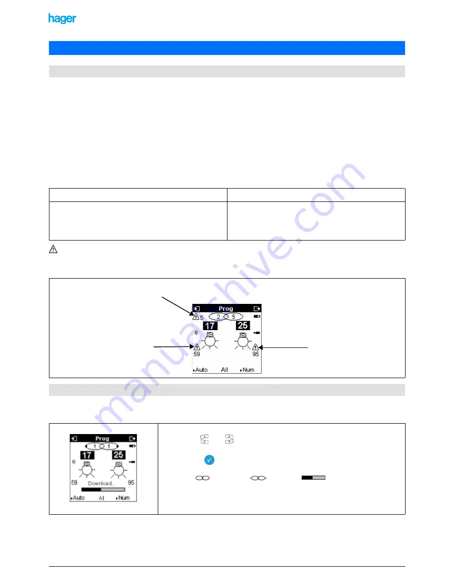
In case of a download fault, the Prog screen indicates faults. A download must then be re-started to make the modification 
effective in the installation.

7.2.1 Removing a simple link or a multiple link

7. Modifying the configuration of an installation

7.1 General indications about the modifications of a KNX installation

Physical modification

Configuration modification

Adding a product.
Removing a product.
Replacing a product.

Creating or removing a link.
Modifying a parameter.
Removing or modifying a function.
Removing or modifying an input or an output.
External memory lost or defective.

Example of a screen showing download faults:

7.2 Removing links

• Select the Prog mode.

• Use the

 and

 keys to select the concerned input and output.

• The link is displayed.

• Press the

 key for a long time to remove the link.

The symbol

 changes into

 and the bar

 appears to indicate that the 

removal of the link is downloaded to the products.

!

 To remove a multiple link, remove the links of each output.

This symbol indicates that 
output 25 is faulty

This symbol indicates that there are a 

total of 5 faults

This symbol indicates that input 17 

is faulty

1

1

1

1

Summary of Contents for tebis TX100

Page 1: ...6T7639a l tebis Configurator TX100 Operating manual...

Page 2: ...ew project 12 3 1 1 Current project 12 3 1 3 Project name 12 3 1 4 Old format project 13 3 2 Projects management 14 3 2 1 Access to the projects management 14 3 2 2 Saving a project 14 3 2 3 Creation...

Page 3: ...installation Input products they send commands pushbuttons switches presence detector etc An input product can have several input channels pushbuttons with several keys etc Output products they recei...

Page 4: ...modules etc Numbering each input and output channel giving a number to each of the 4 keys of a 4 key pushbutton giving a number to each of the 6 output channels of a product with 6 lighting outputs e...

Page 5: ...X100 does not communicate permanently with the installation The complete download is carried out at the end of the configuration The configuration is faster but the installation can only be tested at...

Page 6: ...es or dry cell batteries 2 1 2 Battery life and load 2 Commissioning start up and basic settings of the TX100 2 1 Commissioning the TX100 Remove screw A Open cover B to access the battery compartment...

Page 7: ...an process the two following file types project files with the TXH extension to load a project in the TX100 software update files with the UPD extension to download a new version of the software in or...

Page 8: ...ish is the default language This setting can be changed at any time If the desired language is not displayed carry out an update using the USB stick supplied with the product Insert the USB stick The...

Page 9: ...e left keys to move from one field to the next Press the right keys to increase or decrease the value of the selected field Press the key to confirm your selection The key allows you to return to the...

Page 10: ...This function allows activating or deactivating the use of the ETS group addresses To be taken into consideration the activation or deactivation of the ETS mode must be carried out before the first le...

Page 11: ...y avoiding the selection procedure Select the media coupler to be used by pressing its button until the red indicator turns on 4 s Release the button A Download wait screen is displayed for some secon...

Page 12: ...if an external memory containing projects is connected Press the or key to select Current project to go on with the configuration of the current project which is in the internal memory of the TX100 N...

Page 13: ...he project to the new format The TX100 creates a new project in its internal memory The current project possibly present in the internal memory will be deleted A Warning screen allows authorising or n...

Page 14: ...he current project file of the TX100 in an external memory USB stick or PC for the TX100 USB SM card for the old TX100s with SM card rea der Creation allows creating a new project file The current pro...

Page 15: ...me with the or keys Press the key to confirm your selection The file is saved automatically if the name of the current project is the same as the name of the selected project If the name of the curren...

Page 16: ...eturn to the previous screen Press the YES screen key to delete the current project and authorise the creation of the new project The new project is then created in the internal memory of the TX100 un...

Page 17: ...key to retain the current project and return to the previous screen Press the YES screen key to authorise the replacement of the current project with the new project The new project is then loaded in...

Page 18: ...the new project A wait screen is displayed during the conversion procedure The TX100 loads the project in its internal memory In the case of a TP or a mixed installation with a media coupler the TX10...

Page 19: ...ffect on the file of the current project which is present in the internal memory of the TX100 A Visualisation screen is displayed with a list of Project names Press the or key to select a Project name...

Page 20: ...single operation at the end of the configuration or when switching to On line mode the configuration is globally faster To select the On line or Off line mode press the menu key of the keypad or the M...

Page 21: ...cts RF products bus power supply mains power supply battery power supply refer to the attached table Make sure that all TP products are connected to the bus wire and that the bus is powered 5 2 3 Swit...

Page 22: ...sts in creating the project and assigning the media coupler to the TX100 5 3 Coupling and assigning the TX100 to the installation Switch the installation on Start the TX100 After some seconds the Proj...

Page 23: ...with the installation To detect and assign the media coupler Select the media coupler to be used by pressing its button until the red indicator turns on 4 sec Release the button A Download wait screen...

Page 24: ...or the mixed installations 5 4 1 Learning of the installation with automatic numbering of the outputs In the Installation type screen press the NO screen key since it is an entirely RF installation Go...

Page 25: ...ther outputs Press the right keys to scroll the output numbers and their function symbols The meaning of all function symbols is given in the attachment The numbering of the inputs is performed in Num...

Page 26: ...mbol B Indicates the number of numbered inputs When the TX100 detects an unidirectional RF product it displays specific instructions to number the input Place the TX100 configurator within immediate r...

Page 27: ...uts At the end of the Installation learning phase all TP products and all bidirectional RF products were detected No number has been assigned Press the screen key Num Press the Inputs screen key to st...

Page 28: ...thod 2 Method 2 Press the right keys to select the output To find the output in the installation press the key the action of the product is explained in detail in the Annex 1 Here for example a shutte...

Page 29: ...ns the outputs Select Output numbering Press the key to confirm your selection Select Automatic Press the key to confirm your selection A Write running wait screen is displayed The numbering of the ou...

Page 30: ...numbered Select the Prog mode or the Num mode Press the key to assign a function to this input Press the left keys to select a function among the displayed functions Press the key to confirm your sel...

Page 31: ...ow Example A pushbutton ON function was assigned to the unidirectional RF input number 8 5 6 Creation of links and input of additional parameters Select an input Press the left keys to select the inpu...

Page 32: ...ng another output Repeat the procedure for each new output to be linked After having selected an input and an output To create a simple link between this input and this output for example between inpu...

Page 33: ...th 16 lighting outputs Input 44 has the same function Go to Menu Advanced functions Copy Paste The following screen is displayed Example Preparation of 5 links The last output selected is number 25 Wh...

Page 34: ...ust be set in the Product management menu function of the indicator of a pushbutton label holder backlight duration of the up down stroke of a shutter etc Press the left keys to select input 44 Press...

Page 35: ...ct The change is shown in the screen Menu Device management Device information the symbol is displayed in front of the product reference To download the parameter to the product In Menu Product manage...

Page 36: ...dy configured 5 8 Vizualizing the links The links can be visualized via the inputs by selecting the no or by directly pressing the button corresponding to an input Use the right keys to scroll the out...

Page 37: ...Prog screen indicates faults A download must then be re started to make the modification effective in the installation 7 2 1 Removing a simple link or a multiple link 7 Modifying the configuration of...

Page 38: ...he input was linked with outputs this removal will lead to faults the outputs which were linked with this input and the corresponding products are displayed as faulty So this operation must be followe...

Page 39: ...ludes the following functions Extension of the communication system Grants access to the group address given during programming in Standard mode in order to set up links between a Tebis TX installatio...

Page 40: ...scription of the Expert mode Select Expert Standard to activate the Expert mode Press the YES screen key to confirm The central screen key Expert allows switching between the Prog Easy screen and the...

Page 41: ...s the outputs are marked with the symbol following the output number Select the Prog Expert mode Press the key to switch between the objects list and the inputs outputs numbers Press the left keys to...

Page 42: ...using the numerical keypad Pressing briefly allows deleting a digit pressing for a long time sets the field to 0 The accessible address values depend on whether the ETS mode is activated or not Press...

Page 43: ...roduct object in another application 8 3 Configuring in Expert mode Select the Prog Expert mode Select the object with the and keys Press briefly key The Group Address screen is displayed Select the g...

Page 44: ...gnal confirms the addition of the group address Return to Auto mode Select the input and the output for which an expert link must be created Press the screen key Expert Select the object to be linked...

Page 45: ...4 122 Press the Confirm screen key to return to the Prog Expert screen Download the address with a long key press on The creation of the 2 identical addresses and their download set up the link betwe...

Page 46: ...n Delete allows removing a product from the installation and resetting it to its fac tory condition Device information gives information about a product and gives access to addi tional parameters Repe...

Page 47: ...llow resetting several products at a time This screen displays the list of the products of the installation the figures between brackets correspond to the numbers of the inputs or outputs Only the pro...

Page 48: ...th the or keys Press the key to confirm your selection Press the YES or NO screen key to activate or deactivate the repeater function This screen displays the list of the products of the installation...

Page 49: ...lows re learning an installation This function allows deleting all RF bidirectional and TP products from the installation These products are reset to their factory condition Unidirectional products mu...

Page 50: ...tallation Screen Menu Instal Management Download This function gives general information about the installation This function allows starting or resuming a download for all products of the installatio...

Page 51: ...he software from an external memory Screen Menu Update external memory 9 3 Updating the software of the TX100 Select Update with the or keys Press the key to confirm your selection The key allows you...

Page 52: ...e the external memory and confirm to complete the update The update is completed the TX100 restarts Press the key or Select Update with computer Press the key to confirm your selection Do not use a US...

Page 53: ...639a On the PC paste the update file in directory TX100 HAGER The following screen indicates that the link from the TX100 to the PC is being established The following screen is displayed when the link...

Page 54: ...esume procedure Validation the TX100 validates the learnt project file and converts it into a normal project file To regenerate their links the unidirectional inputs must be numbered after validation...

Page 55: ...ation of the Learn installation process Press the key to confirm your selection The TX100 displays a New project screen and assigns it a name here Installation 002 The screen key allows you to return...

Page 56: ...er Press the button of the media coupler until the red indicator lights up 4 sec Release the button A Download wait screen is displayed for some seconds A sound signal is emitted when the selection is...

Page 57: ...ype screen is displayed The following Learn installation screen is displayed when the NO screen key is pressed Press the YES screen key if the installation includes one or more bidirectional RF produc...

Page 58: ...Go to Screen Menu Instal Management Learn Installation The Learn installation screen displays the total number of RF products found the total number of TP products found the Error lines indicate the n...

Page 59: ...A screen indicates that the validation turns the installation definitively into a normal installation It will not be possible any more to start an additional learning loop or to resume in case of err...

Page 60: ...X100 Screen Menu Screen Menu RF tools 9 5 2 RF noise measurement Screen Menu RF tools RF noise 9 5 Measuring tools Select RF tools using the or key Press the key to confirm your selection The key allo...

Page 61: ...start of the measuring cycle if necessary a low battery alert for the active transmitter Press the Start screen key to restart the measuring cycle Press the Stop screen key to stop the measuring cycle...

Page 62: ...behaves like an input It is possible to test the links set up with this input There are 2 ways to start a simulation In Prog mode press the key of the keypad for a long tyme Press the Menu access key...

Reviews: