3
Fit sliding table assembly
Unpack the long box of all extra pieces leaving sliding table
assembly in crate.
Remove the 4 sides of the crate
With the aid of a forklift remove wrapped sliding table assembly by
sliding onto fork tines
Carefully cut along length of table and remove packaging.
Check table sliding lock lever ( RH front of table assembly when up
correct way) is in the locked position!
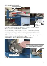
Remove the access cover off the right hand rear of saw bench
and open up electrical cabinet. (Ensure machine is not connected to power)
Position fork in front of saw bench and with assistance roll over table assembly onto its top.
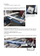
Lift off and position table on saw body locating 3 x sliding pins in the 3 x holes on table base.
Screw in and finger tighten only each end attachment bolt.
Being careful not to disturb any electrical wiring.
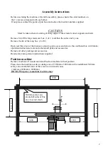
Table base assembly can now be pushed Left or Right to position it in the correct place
NB the positioning of the table is to finish as shown
( 720 mm from Right hand side of machine base)
Table lock lever in
lock position
Sliding pin
under table
base
Hole in machine
base
720mm
Access cover

