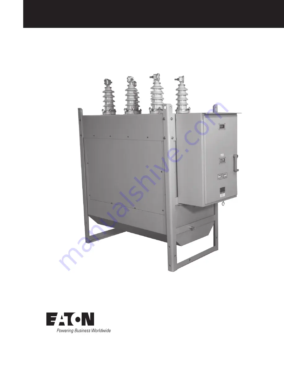
Type VSA12, VSA12B, VSA16, VSA20, and VSA20A operation and
installation instructions
COOPER POWER
SERIES
Reclosers
MN280063EN
Effective May 2017Supersedes October 2002 (S280-45-1)
Page 1: ...Type VSA12 VSA12B VSA16 VSA20 and VSA20A operation and installation instructions COOPER POWER SERIES Reclosers MN280063EN Effective May 2017 Supersedes October 2002 S280 45 1...
Page 2: ...FITNESS FOR A PARTICULAR PURPOSE OR MERCHANTABILITY OTHER THAN THOSE SPECIFICALLY SET OUT IN ANY EXISTING CONTRACT BETWEEN THE PARTIES ANY SUCH CONTRACT STATES THE ENTIRE OBLIGATION OF EATON THE CONTE...
Page 3: ...gs and electrical mechanical Specifications 2 Dimensions and weights Dimensions and weights 3 Installation Installation procedure 4 Heaters 5 240 vac power connections 6 Remove recloser from service 6...
Page 4: ...hen working around high voltage lines and equipment and support our Safety For Life mission Safety information DANGER Hazardous voltage Contact with hazardous voltage will cause death or severe person...
Page 5: ...carrier for shipment Upon receipt inspect the carton for signs of damage Unpack the control and inspect it thoroughly for damage incurred during shipment If damage is discovered file a claim with the...
Page 6: ...Circuit Interrupting Rating Maximum X R Ration Number of Unit Operations 15 20 45 55 90 100 4 8 16 88 112 32 Total 232 Table 5 Electrical Specifications Description Trip Solenoid Operating voltage Vdc...
Page 7: ...298 11 75 K 1080 42 5 1257 49 5 L 413 16 25 514 20 25 M 159 6 25 260 10 25 N 108 4 25 210 8 25 All dimensions are mm inches Dimensions shown are approximate Figure 1 Outline dimensions and weights Mo...
Page 8: ...Perform high potential withstand tests Prior to installing the VSA recloser with the recloser in the OPEN position perform high potential withstand tests across each open interrupter assembly Refer to...
Page 9: ...VSA20A bushings are equipped with 1 1 4 12 UNF 2A threaded studs Figure 3 Typical recloser connections with switches to facilitate maintenance and with complete surge protection 7 Block ground sensing...
Page 10: ...utility procedures regarding removal of recloser from service AS Auxiliary Switch 152 Spring Position Switch 24 Vdc SP1 152 CC Close Coil Solenoid D Diodes 1N3209 152 SP2 Spring Position Switch 240 V...
Page 11: ...t Heaters Interrupter Enclosure 5K 3 5K Battery Charger accessory KA58VSM2 152 MCS 152 aa1 152 SP2 152 bb1 152 SP1 152 LS 152 CC 152 TC 152 a2 152 a1 2 1 3 4 6 8 7 5 Receptacle and Plug 1R X1K X2J X1...
Page 12: ...wired to a separate six point terminal block in the operator mechanism cabinet Figure 5 The available current ratios and terminal block terminations are shown in Table 8 Figure 6 Position of shorting...
Page 13: ...ontrol cable is wired to the accessory which transforms the control signal to trip and close the recloser Refer to Figures 8 and 9 Table 9 Cable Lengths for Substation Battery Power Interface Accessor...
Page 14: ...in Contacts are Open 152 H Manual Trip and Reset Switch when not in reset position will prevent a close 152 a Auxiliary Switch Contact Open when Main Contacts Open Figure 9 Substation Battery Power In...
Page 15: ...Mounting Electronic Control see detail Alternate Control Mounting for clarity operator on front of recloser is not shown Standard Control Cabinet Mounting Brackets FRONT KA55VS2 KA55VS4 double size co...
Page 16: ...75 C 406 16 483 19 D 292 11 5 318 12 5 All dimensions are mm inches Dimensions shown are approximate Model kg lbs VSA 12 12B 16 20 272 600 VSA20A 381 840 Figure 11 Outline dimensions and weights with...
Page 17: ...igure 12 Type VSA20 vacuum recloser with inspection cover removed Figure 13 VSA20 vacuum interrupter assembly Recloser tripping and closing are initiated by signals from the recloser control unit When...
Page 18: ...ure 14 Manual closing Closing springs must be charged prior to manual closing operation see the Testing Operation section of this manual There are two ways to manually close the recloser Refer to Figu...
Page 19: ...additional information and specific maintenance requirements including periodic maintenance inspection procedures refer to the maintenance manual Testing operation This recloser is used with microproc...
Page 20: ...nside of the operator cabinet door through the hole in the right hand side of the operator cabinet sealed with a bolt nut seal and onto the drive shaft see Figure 15 v Crank the motor in a countercloc...
Page 21: ...ential withstand tests at 37 5 kV rms 60 Hz or at 50 kV for 60 seconds See Figure 16 for test connection diagrams Test 1 1 Close the recloser contacts 2 Ground the recloser 3 Connect terminals 2 4 and...
Page 22: ...ative Replacement parts Replacement parts for Eaton reclosers are available through the factory Service Department To order replacement parts refer to the maintenance manual and S260 01 through S280 0...
Page 23: ...19 type vsa12 vsa12b vsa16 vsa20 and vsa20a operation and installation instructions MN280063EN May 2017 This page is intentionally blank...
Page 24: ...States Eaton com cooperpowerseries 2017 Eaton All Rights Reserved Printed in USA Publication No MN280063EN KA2048 0046 Rev 02 Eaton is a registered trademark All trademarks are property of their resp...