


15
TRT
TILTING ROTARY
TABLE
TRT
O
M
PERATOR’S
ANUAL
TILTING ROTARY
TABLE
96-5048 rev E
June 2002
2.4 T
HE
R
EMOTE
I
NPUT
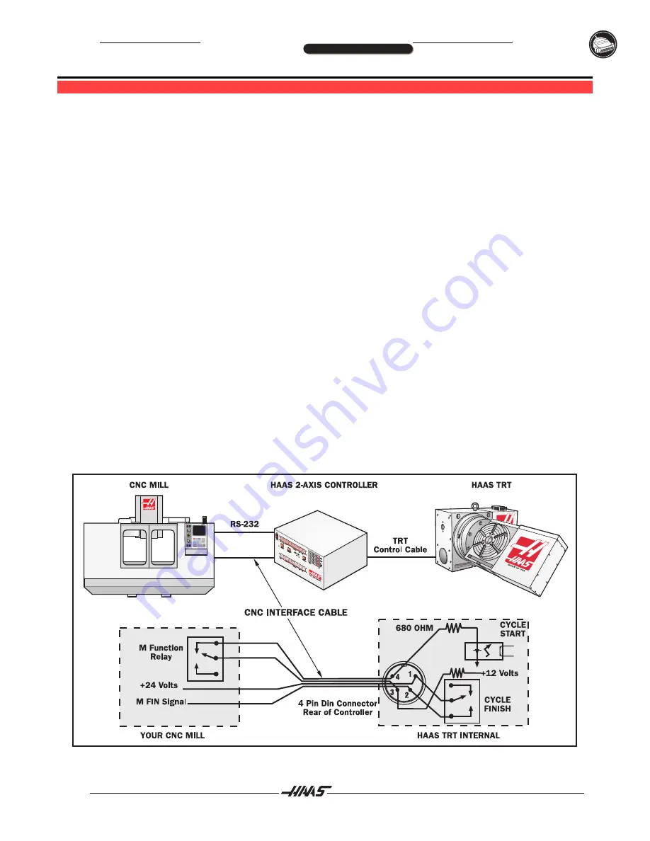
The CNC Interface Cable provides a basic method of communication between a non-Haas mill and Haas Servo
Control/Rotary Head. Since most CNC machine tools are equipped with spare M-codes, Semi-fourth axis
machining can be achieved by connecting one end of the CNC Interface Cable to any one of these spare relays
(switches), and the other to a Haas Servo Control unit. Indexing commands for the rotary unit are stored only in
the Servo Controls memory, and each pulse of the host machines relay triggers the control to index to its next
programmed position. After finishing the index, the Servo Control signals that it has finished and is ready for the
next pulse.
A remote socket is provided on the back panel of the control unit. The remote input consists of a
cycle start
line and a
cycle finish
line. To connect to the remote, you will need a connector supplied by HAAS (or one
obtained from a local source) that can be used to trigger the controller from any one of several sources. The
cable connector used is a male four-pin DIN connector. The Amphenol part number is 703-91-T-3300-1. The part
number of the panel receptacle in the control box is 703-91-T-3303-9.
Cycle Start
The figure shows the connector as viewed from the rear panel of the control unit. When pins 3 and 4 are
connected to each other for a minimum of 0.1 seconds, the control will index the head one cycle or step. To
index again, pins 3 and 4 must be opened for a minimum of 0.1 seconds. Under no circumstances should
power be applied to pins 3 and 4. A relay closure is the safest way to interface the control to your equipment.
When a
cycle start
is implemented, pin 3 supplies a positive 12 volts at 20 milliamps and pin 4 is connected to
the diode of an opto-isolator that grounds to chassis. Connecting pin 3 to pin 4 causes a current to flow through
the diode of the opto-isolator, triggering the control.
If the control is used around high frequency equipment such as electric welders or induction heaters, you will
need to use shielded wire to prevent false triggering by radiated EMI (electromagnetic interference). The shield
should be attached to earth ground.
A Typical CNC Interface.
SETTING UP TRT
Summary of Contents for TRT210
Page 2: ...Haas Technical Publications Manual_Archive_Safety_Pages Rev A June 6 2013...
Page 6: ...MILL WARNING DECALS Haas Technical Publications Manual_Archive_Safety_Pages Rev A June 6 2013...
Page 7: ...LATHE WARNING DECALS Haas Technical Publications Manual_Archive_Safety_Pages Rev A June 6 2013...