Installation Manual
H3C WA2200 Series WLAN Access Points
Chapter 4 Installation of Outdoor APs
4-17
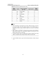
Table 4-2
RJ-45 crossover Ethernet cable pinouts
Pin of
RJ-45
connector
Signal
Category-5 twisted
pair cable
Signal direction
Pin of
RJ-45
connector
1 Tx+
White
(orange)
Æ
3
2 Tx-
Orange
Æ
6
3 Rx+
White
(green)
Å
1
4 —
Blue
— 4
5 —
White
(blue)
— 5
6 Rx-
Green
Å
2
7 —
White
(brown)
— 7
8 —
Brown
— 8
Note:
z
When distinguishing or preparing these two types of Ethernet cables, you can refer
to the above tables. Since the Ethernet interface of the WA2200 series is
auto-sensing, these two types of Ethernet cables can be used for the Ethernet
interface.
z
Refer to Table 4-1 and Table 4-2 to arrange the wire sequence when preparing an
Ethernet cable. Otherwise, the communication quality will not be high, even if the
devices at both ends can communicate.
z
The Ethernet cable should be equipped with a waterproof sheath when routed
outdoors. If possible, cable routing in waterproof tubes is recommended.
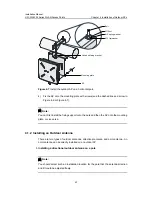
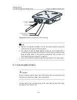
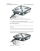
3) Insert the Ethernet cable connector into the Ethernet interface, as shown in Figure
4-17.


