H3C H3C S5100-SI Installation Manual Download Page 79

Installation Manual 
H3C S5100-SI/EI Series Ethernet Switches 

Chapter 4  Powering on the Switch for the First Time


4-4 

Choose [Properties] in the HyperTerminal dialog box to enter the properties window. 

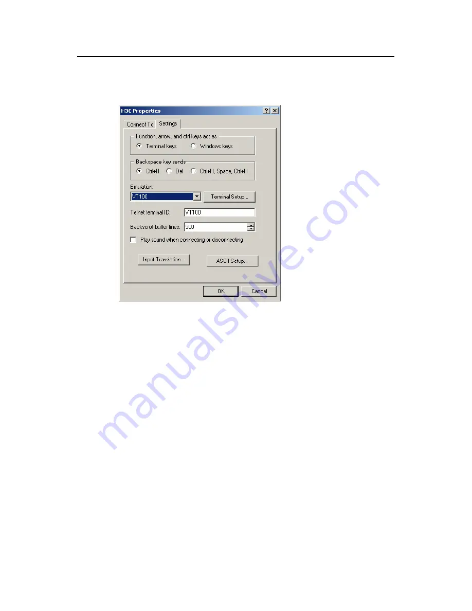
Click [Settings] to enter the following properties setting window, select VT100 as the 

terminal emulation, and then click <OK>.  


Figure 4-6 

Setting terminal emulation in properties setting window 

4.4  Booting the Switch 

4.4.1  Checking before Powering on the Switch 

Before powering on the switch, verify that:  

z


The power cords are properly connected.  

z


The power supply voltage is consistent with that required by the switch. 

z


The console cable is properly connected; the terminal (which can be a PC) used 

for configuration has been started; and the configuration parameters have been 

set.  

4.4.2  Powering on the Switch 

All the S5100 series Ethernet switches have the same BOOT ROM display style. This 

document uses the Boot ROM display of S5100-48P-EI as an example: 

Summary of Contents for H3C S5100-SI

Page 1: ...H3C S5100 SI EI Series Ethernet Switches Installation Manual Hangzhou H3C Technologies Co Ltd http www h3c com Manual Version 20080123 C 1 05...

Page 2: ...InnoVision and HUASAN are trademarks of Hangzhou H3C Technologies Co Ltd All other trademarks that may be mentioned in this manual are the property of their respective owners Notice The information i...

Page 3: ...s 2 Preparing for Installation Introduces the installation preparation and precaution of S5100 SI EI Series Ethernet Switches 3 Installing the Switch Introduces the procedures to install an S5100 SI E...

Page 4: ...rd slashes For example File Create Folder II Symbols Convention Description Warning Means reader be extremely careful Improper operation may cause bodily injury Caution Means reader be careful Imprope...

Page 5: ...EI Ethernet Switch 1 16 1 3 8 S5100 16P PWR EI Ethernet Switch 1 18 1 3 9 S5100 26C PWR EI Ethernet Switch 1 20 1 3 10 S5100 50C PWR EI Ethernet Switch 1 21 1 4 LEDs 1 23 1 4 1 Power LED PWR 1 23 1 4...

Page 6: ...ord 3 16 3 5 2 Connecting DC Power Cord 3 17 3 5 3 Connecting Grounding Wire 3 19 3 6 Connecting Console Cable 3 21 3 6 1 Console Cable 3 21 3 6 2 Connecting Console Cable 3 22 3 7 Installing and Remo...

Page 7: ...through Ethernet Port 5 8 5 2 4 Loading Software Using FTP Through Ethernet Port 5 9 5 3 Remote Software Loading 5 11 5 3 1 Remote Loading Using FTP 5 11 5 3 2 Remote Loading Using TFTP 5 13 Chapter 6...

Page 8: ...ting data center server clusters The H3C S5100 series come in two series S5100 SI and S5100 EI which are available in the following models Table 1 1 H3C S5100 SI EI series Series Model 10 100 100 0Bas...

Page 9: ...16 19 13 S5100 16P SI S5100 16P EI S5100 16P PWR EI 20 15 25 22 26 24 27 21 S5100 24P SI S5100 24P EI S5100 26C EI S5100 26C PWR EI 28 23 49 46 50 48 51 45 S5100 48P SI S5100 48P EI S5100 50C EI S510...

Page 10: ...D 6 Ethernet port mode switching LED 7 Port status LED mode switch Figure 1 1 Front panel of an S5100 8P SI Ethernet switch II Rear Panel 1 AC power input 2 Grounding terminal Figure 1 2 Rear panel of...

Page 11: ...V Cooling system An S5100 8P SI Ethernet switch provides one fan for heat dissipation 1 2 2 S5100 16P SI Ethernet Switch I Front panel An S5100 16P SI Ethernet switch provides 16 x 10 100 1000Base T a...

Page 12: ...SI Ethernet switch II Rear panel 1 AC power input 2 Grounding terminal Figure 1 5 Rear panel of an S5100 16P SI Ethernet switch III Side panel An S5100 16P SI Ethernet switch provides a lock hole for...

Page 13: ...ts forming the Combo port can be used at a time Table 1 2 shows the mapping relations between the ports forming the Combo port Figure 1 6 shows the front panel of an S5100 24P SI Ethernet switch 1 10...

Page 14: ...ombo port can be used at a time Table 1 2 shows the mapping relations between the ports forming the Combo port Figure 1 8 shows the front panel of an S5100 48P SI Ethernet switch 1 1 2 3 4 5 6 7 1 10...

Page 15: ...ort on the front panel Figure 1 10 shows the front panel of an S5100 8P EI Ethernet switch 1 10 100 1000Base T autosensing Ethernet port status LEDs 2 1000Base X SFP port status LED 3 Console port 4 7...

Page 16: ...ernet switch provides 16 x 10 100 1000Base T autosensing Ethernet ports four 1000Base X SFP ports and one console port on the front panel An SFP port and its corresponding 10 100 1000Base T autosensin...

Page 17: ...ed voltage range 100 VAC to 240 VAC 50 Hz or 60 Hz Max voltage range 90 VAC to 264 VAC 47 Hz to 63 Hz V Cooling system An S5100 16P EI Ethernet switch provides one fan for heat dissipation 1 3 3 S5100...

Page 18: ...input 3 Grounding terminal Figure 1 15 Rear panel of an S5100 24P EI Ethernet switch III Power supply system An S5100 24P EI switch provides AC power input and RPS DC input The AC and DC power inputs...

Page 19: ...rts and one console port on the front panel An SFP port and its corresponding 10 100 1000Base T autosensing Ethernet port form a Combo port That is only one of the two ports forming the Combo port can...

Page 20: ...100 VAC to 240 VAC 50 Hz or 60 Hz Max voltage range 90 VAC to 264 VAC 47 Hz to 63 Hz z DC input Rated voltage range 48 VDC to 60 VDC Max voltage range 36 VDC to 72 VDC IV Cooling system An S5100 48P E...

Page 21: ...net switch II Rear panel An S5100 26C EI Ethernet switch provides AC input DC input and two 10 Gbps interface slots on the rear panel as shown in Figure 1 19 1 AC power input 2 DC power input 3 10 G i...

Page 22: ...tch provides 48 x 10 100 1000Base T autosensing Ethernet ports four 1000Base X SFP ports and one console port on the front panel An SFP port and its corresponding 10 100 1000Base T autosensing Etherne...

Page 23: ...input alone or the DC power input alone Make sure you use an RPS module recommended by H3C as the DC power input z AC input Rated voltage range 100 VAC to 240 VAC 50 Hz or 60 Hz Max voltage range 90...

Page 24: ...I Ethernet switch II Rear panel 1 AC power input 2 Grounding terminal Figure 1 23 Rear panel of an S5100 8P PWR EI Ethernet switch III Side panel An S5100 8P PWR EI Ethernet switch provides a lock hol...

Page 25: ...5 4 W for the connected devices The maximum output power for the whole system is 65 W VI Cooling system An S5100 8P PWR EI Ethernet switch provides two fans for heat dissipation 1 3 8 S5100 16P PWR EI...

Page 26: ...ax voltage range 90 VAC to 264 VAC 47 Hz to 63 Hz V PoE S5100 16P PWR EI Ethernet switches support PoE They can be connected to remote PDs such as IP phones WLAN APs Security and Bluetooth APs over tw...

Page 27: ...rts forming the Combo port can be used at a time Table 1 2 shows the mapping relations between the ports forming the Combo port Figure 1 26 shows the front panel of an S5100 26C PWR EI Ethernet switch...

Page 28: ...an also supply power to some of the PDs incompatible with 802 3af standards z An S5100 26C PWR EI Ethernet switch can provide power supplies through its 24 fixed Ethernet electrical ports over a dista...

Page 29: ...erminal 5 DC power input Figure 1 29 Rear panel of an S5100 50C PWR EI Ethernet switch III Power supply system An S5100 50C PWR EI switch provides AC power input and RPS DC input The AC DC power input...

Page 30: ...xed Ethernet electrical ports over a distance of up to 100 m 328 feet z Each Ethernet port on an S5100 50C PWR EI Ethernet switch provides a maximum output power of 15 4 W for the connected devices Wh...

Page 31: ...One or more ports have failed in POST or other non fatal errors have been detected Power LED PWR OFF The switch has been powered off 1 4 2 DC Power Supply LED RPS The RPS LED is a yellow green indica...

Page 32: ...port status LEDs Port mode LED status Description ON The port is connected at 1 000 Mbps Green Blinking 30 ms per packet The port is receiving or sending data at 1 000 Mbps ON The port is connected a...

Page 33: ...Blinking 3 Hz The power required exceeds the maximum output power of the port or the available power of the switch is insufficient ON PoE malfunctioned and the power supply failed Yellow Blinking 3 H...

Page 34: ...data at 10 100 Mbps Yellow Blinking 3 Hz Port POST has failed Rate mode OFF The port is not connected ON The port is working in full duplex mode Green Blinking The port is receiving or sending data in...

Page 35: ...odule has been installed and connected Green blinking The module is receiving or sending data Yellow blinking 3 Hz Module POST has failed Module LED MOD1 or MOD2 Yellow ON The device does not support...

Page 36: ...tates clockwise around the display during the downloading procedure Fan failure Red ON An F is displayed Unit ID Green ON A 1 is displayed Cluster Manage ment Green ON A C is displayed on command swit...

Page 37: ...Service ports 8 10 100 1000Bas e T autosensing Ethernet ports 2 1000Base X SFP ports 16 10 100 1000Bas e T autosensing Ethernet ports 4 Gigabit SFP Combo ports 24 10 100 1000 Base T autosensing Ethern...

Page 38: ...100 1000 Base T autosensing Ethernet ports 4 Gigabit SFP Combo ports 48 10 100 1000 Base T autosensing Ethernet ports 4 Gigabit SFP Combo ports Managemen t port One console port Power supply system Th...

Page 39: ...voltage range 100 VAC to 240 VAC 50 Hz or 60Hz Max voltage range 90 VAC to 264 VAC 47 Hz to 63 Hz DC input Rated voltage range 48 VDC to 60 VDC Max voltage range 36 VDC to 72 VDC Max power consumptio...

Page 40: ...I series support AC input and DC input AC input Rated voltage range 100 VAC to 240 VAC 50 Hz or 60Hz Max voltage range 90 VAC to 264 VAC 47 Hz to 63 Hz DC input for S5100 26C PWR EI and S5100 50C PWR...

Page 41: ...and restoration temperatures Table 1 14 PoE protection temperatures and restoration temperatures Item PoE protection temperature C PoE restoration temperature C S5100 8P PWR EI 73 68 S5100 16P PWR EI...

Page 42: ...z Only the S5100 26C EI S5100 50C EI S5100 26C PWR EI and S5100 50C PWR EI switches support XENPAK optical modules z BIDI modules must be used in pair For example if an SFP GE LX SM1310 BIDI is used...

Page 43: ...K1 50 cm 19 7 in CX4 stack cable 50 cm LS5M2STK2 100 cm 39 4 in CX4 stack cable 1 0 m LS5M2STK3 300 cm 118 1 in CX4 stack cable 3 0 m 1 9 Ordering DC Power cords Table 1 18 Ordering information for DC...

Page 44: ...ctrical shocks z When replacing interface cards wear ESD preventive gloves to avoid damaging the cards 2 2 Installation Site The S5100 series must be used indoors You can mount your switch in a rack o...

Page 45: ...The following table lists the dust concentration limit Table 2 1 Dust concentration limit in the equipment room Substance Unit Concentration limit Dust Particles m 3 10 4 No visible dust on the tablet...

Page 46: ...lding when necessary for example use shielded interface cables z Route interface cables only indoors to prevent signal ports from getting damaged by overvoltage or overcurrent caused by lightning stri...

Page 47: ...h You can mount an H3C S5100 switch into a 19 inch standard rack in one of the following four ways z Use front mounting ears z Use front mounting ears and rear mounting ears z Use front mounting ears...

Page 48: ...tch is greater than 300 mm 11 8 in the front mounting ears only secure the switch rather than bear its weight z Guide rails purchased from H3C apply only to standard racks 1 000 mm 39 4 in deep Use ot...

Page 49: ...see Table 3 3 Table 3 3 Selection of mounting ear for the H3C S5100 series Ethernet Switches Model Physical dimensions H x W x D Configuration type of front mounting ear Configuration type of rear mo...

Page 50: ...ole 2 Used to fix the guide rail to the front bracket Figure 3 3 Appearance of a guide rail Note No guide rails are delivered with the device See Table 3 1 and Table 3 2 to decide whether any guide ra...

Page 51: ...and a Tray Follow these steps to install a switch into a 19 inch standard rack with front mounting ears and a tray 1 Wear an ESD preventive wrist strap to check the grounding and stability of the rack...

Page 52: ...Figure 3 4 3 Take out the load bearing screws packed together with the rear mounting ears and place them in a proper position on the sides of the switch as shown in Figure 3 6 Screw 1 Load bearing scr...

Page 53: ...the cabinet gently as shown in Figure 3 8 Screw 1 Screw 2 Rear mounting ear Front mounting ear Front square holed bracket Rear panel Rear square holed bracket Screw 1 Used to bear the weight Screw 2 U...

Page 54: ...Load bearing screw Figure 3 9 Effect diagram of front and rear mounting ear installation 1 6 Fix the other end of the front mounting ears to the front brackets with screws and captive nuts and ensure...

Page 55: ...n 2 3 1 6 Use Front Mounting Ears and Guide Rails Follow these steps to install a switch into a 19 inch standard rack with front mounting ears and guide rails 1 Wear an ESD preventive wrist strap to c...

Page 56: ...brackets on both sides of the cabinet with M5 self tapping screws as shown in Figure 3 12 Figure 3 12 Install guide rails 4 Hold the two sides of the switch and slide it gently along the guide rails i...

Page 57: ...ng ears to the front brackets of the cabinet with M6 screws and captive nuts and ensure that the front mounting ears and guide rails have fixed the switch in the cabinet securely as shown in Figure 3...

Page 58: ...ion z No heavy object is placed on the switch z A vertical distance of at least 1 5 cm 0 6 in is kept between devices if you need to stack switches one upon another 3 3 Wall Mounting You can mount the...

Page 59: ...oles and keep only the edges outside the wall 3 As shown in Figure 3 17 drive screws into the anchor kits keeping the inside of screw head at least 1 5 mm 0 06 in away from the edge of the anchor kit...

Page 60: ...ion procedure Follow these steps to complete magnet mounting 1 As shown in Figure 3 19 use a Phillips screwdriver to pass the countersunk head screw through the round hole at the central of the perman...

Page 61: ...Avoid installing the device at a high place because personal injuries or equipment damage may occur in case of a falloff z Avoid frequently moving the desk mounted device because such movements may da...

Page 62: ...e fact Neutral point Zero line Live line Neutral point Zero line Live line Figure 3 20 Recommended AC power socket II Connecting AC power cord 1 Connect one end of the grounding wire delivered with th...

Page 63: ...s the power is properly connected Caution Before powering on the switch you should properly connect the grounding wire 3 5 2 Connecting DC Power Cord NULL NULL 48 V working ground 48 V to 60 V NULL Re...

Page 64: ...ble ties to bind the two power cords to the protruding part at the back of the air filter as shown in Figure 3 23 Connector parts Screw 1 Screw 2 Chassis Connector parts Screw 1 Screw 2 Chassis Figure...

Page 65: ...When a grounding strip is available at the installation site attach one end of the yellow green grounding wire of the switch to the grounding screw on the grounding strip and fasten the captive nut N...

Page 66: ...g body into the earth For an AC powered switch if none of the above two conditions is available ground it through the PE wire of the AC power supply In this case make sure this PE wire is well connect...

Page 67: ...rip 3 48V 4 RTN strip 5 RTN 6 PGND strip 7 Grounding to the earth 8 Grounding wire 9 Screw 10 Ethernet switch 11 DC power input Figure 3 28 Ground the switch through the PGND of the power cabinet 3 6...

Page 68: ...onnect the DB 9 female connector of the Console cable to the serial port of the PC or the terminal device used to configure the switch Step 2 Connect the RJ 45 connector of the Console cable to the Co...

Page 69: ...llation Step 1 Put on an ESD preventive wrist strap and verify the ESD preventive wrist strap properly grounded Then take out the XFP interface module from the package Step 2 Loosen the mounting screw...

Page 70: ...emoved filler panel properly for future use z When tightening the fastening screws at both sides of the optional module with a screwdriver or an electric screwdriver make sure that the torque is not b...

Page 71: ...with your hands z After removing an optional module if no new module is to be installed install the filler panel as soon as possible to prevent dust and ensure the normal ventilation in the switch 3...

Page 72: ...take out the XENPAK optical module from the package Step 2 Loosen the two mounting screws on the small cover plate in the middle on the filler panel with a screwdriver and remove the small cover plate...

Page 73: ...optical module on the filler panel Note z Keep the removed small cover plate properly for future use z When tightening the fastening screws at both sides of the optional module with a screwdriver or...

Page 74: ...ll 10GE stack cards Step 1 Put on an ESD preventive wrist strap and verify the ESD preventive wrist strap properly grounded Then take out the dedicated stack cable from the package Step 2 Insert the p...

Page 75: ...han 0 4N m z When connecting a stack cable make sure that the bending radius of cable is at least eight times of the cable diameter 3 9 Verifying the Installation After completing the installation ver...

Page 76: ...C Console cable Switch Console port Serial port Figure 4 1 Network diagram for the first power on of the switch 4 2 Connecting the Console Cable Step 1 Plug the DB 9 female connector of the console ca...

Page 77: ...ct Start Programs Accessories Communications HyperTerminal to enter the HyperTerminal window where click the icon to establish a new connection The connection description interface appears as shown be...

Page 78: ...serial port and the system pops up the following interface On the interface set Bits per second to 9600 Data bits to 8 Parity to none Stop bits to 1 and Flow control to none Figure 4 4 Setting serial...

Page 79: ...tting window 4 4 Booting the Switch 4 4 1 Checking before Powering on the Switch Before powering on the switch verify that z The power cords are properly connected z The power supply voltage is consis...

Page 80: ...ormal startup and fast startup The normal startup mode takes a little longer time than the fast startup mode because of more self test operations z By default the system starts up in fast startup mode...

Page 81: ...is available Press ENTER to get started Note The setting takes effect only for the first reboot if you choose 7 Skip current configuration file in the BOOT MENU 4 4 3 Changing the Startup Mode By def...

Page 82: ...lete file from flash 5 Modify bootrom password 6 Enter bootrom upgrade menu 7 Skip current configuration file 8 Set bootrom password recovery 9 Set switch startup mode 0 Reboot Enter your choice 0 9 E...

Page 83: ...0000 Initialize LS51LTSG OK SDRAM fast selftest OK Flash fast selftest OK CPLD selftest OK Switch chip selftest OK Port 1 has no module Port 2 has no module Port 3 has no module Port 4 has no module P...

Page 84: ...on the Switch for the First Time 4 9 Note The H3C Series Switches provides abundant command views For detailed descriptions about the configuration commands and CLI refer to H3C S5100 Series Ethernet...

Page 85: ...introduces how to load The Boot ROM and host software into a switch locally and how to do this remotely 5 1 Introduction to Loading Modes You can load the software locally by using z XModem through co...

Page 86: ...g process 5 2 1 Boot Menu Starting H3C S5100 48P EI BOOTROM Version 616 Copyright c 2004 2007 Hangzhou H3C Technologies Co Ltd Creation date Apr 16 2007 11 29 53 CPU type BCM5836 CPU Clock Speed 200MH...

Page 87: ...hecksum and CRC and error packet retransmission mechanism generally the maximum number of retransmission attempts is ten The XModem transmission procedure is completed by the cooperation of a receivin...

Page 88: ...nter 5 the 115200 bps rate is chosen and the system displays the following information Download baudrate is 115200 bps Please change the terminal s baudrate to 115200 bps and select XMODEM protocol Pr...

Page 89: ...ROM and Host Software Loading 5 5 Figure 5 1 Properties dialog box Figure 5 2 Console port configuration dialog box Step 5 After setting the baud rate you need to disconnect and the reconnect HyperTer...

Page 90: ...onnect and reconnect the terminal emulation program Step 6 Press Enter to start downloading the program The system displays the following information Now please start transfer file with XMODEM protoco...

Page 91: ...s updating now done instead of the prompt Your baudrate should be set to 9600 bps again Press enter key when ready Step 10 Reset HyperTerminal s baud rate to 9600 bps refer to Step 4 and 5 Then press...

Page 92: ...Ethernet port TFTP Server TFTP Client Switch PC Server Console port Ethernet port TFTP Server Figure 5 6 Local loading using TFTP Step 1 As shown in Figure 5 6 connect the switch through an Ethernet p...

Page 93: ...Loading done Bootrom updating done III Loading host software Step 1 Select 1 in Boot Menu The system displays the following information 1 Set TFTP protocol parameter 2 Set FTP protocol parameter 3 Se...

Page 94: ...assword and specify the path of the program to be downloaded Step 3 Run the terminal emulation program on the configuration PC Start the switch Then enter the Boot Menu At the prompt Enter your choice...

Page 95: ...me as those for loading the Boot ROM software except that the system gives the prompt for host software loading instead of Boot ROM loading 5 3 Remote Software Loading If your terminal is indirectly c...

Page 96: ...ch H3C boot boot loader s5100 bin H3C display boot loader Unit 1 The current boot app is s5100 bin The main boot app is s5100 bin The backup boot app is Step 4 Restart the switch H3C reboot Note Befor...

Page 97: ...Host Software Loading 5 13 5 3 2 Remote Loading Using TFTP The remote loading by using TFTP is similar to the remote loading by using FTP The only difference is that it is TFTP that you use when loadi...

Page 98: ...ith a baud rate other than 9600 bps when using TFTP verify that you have specified the correct server and switch IP addresses the correct name of the software to be loaded and the correct working path...

Page 99: ...inal If the configuration system has any faults there will not be any screen display at the configuration terminal or the displayed characters will be totally illegible I Troubleshooting when there is...

Page 100: ...Switches Table of Contents i Table of Contents Appendix A Lightning Protection of the Switch A 1 A 1 Installation of Lightning Arrester for AC Power Socket Strip with Lightning Protection A 1 A 2 Inst...

Page 101: ...due to lightning strike You can use cable clips and screws to fasten the lightning arrester for AC power on the cabinet workbench or the wall of equipment room Mainboard Grounding and polarity indicat...

Page 102: ...power socket in the equipment room it means that arrester is not well grounded If it is adverse to that of the power socket in the equipment room it means that the power socket of the arrester is set...

Page 103: ...acts well with the grounding screw of chassis Step 4 According to the instruction of arrester for network port connect the arrester with switch by the cables be carefully with the cable direction Outd...

Page 104: ...port will be affected z Lightning arrester for network port is installed in reverse direction In practice the IN end should be connected to the outdoor network cable and the OUT end to the network por...

Reviews: