8
Mounting the router in the rack
WARNING!
•
Do not hold the handle of a fan tray or power module, air vents, or the handle on the real panel to
move the router. Doing so might cause equipment damage or even bodily injury.
•
The router is heavy. As a best practice, use a mechanical lift to move it.
•
After placing the router on the slide rails, do not leave go of your hands immediately because this
might tip the router, damaging the router or even causing bodily injury.
This task requires a minimum of two people.
To mount the router in the rack:
1.
Move the chassis to face the rear of the chassis towards the front of the rack.
2.
Lift the router by using the handles or supporting the bottom of the chassis until the bottom of
the router is a little higher than the slide rails on the rack.
3.
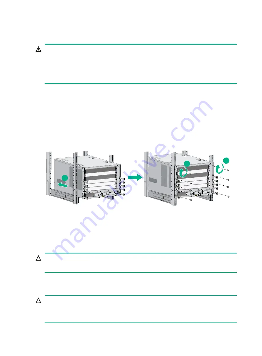
Place the router on the slide rails and slide the router along the slide rails until the mounting
brackets on the router touch the front rack posts.
4.
Attach the chassis to the rack with mounting screws.
Figure 9 Installing the chassis in the rack
If the mounting holes in the mounting brackets cannot align with the cage nuts on the rack, verify that
the bottom edge of the slide rail aligns with the middle of the narrower metal area between holes and
that the cage nuts are installed in the correct holes.
Grounding the router
CAUTION:
Before you use the router, connect the grounding cable correctly to guarantee lightning protection
and anti-interference of the router.
Grounding the router with a grounding strip
CAUTION:
•
Use the supplied grounding cable (yellow-green grounding cable).
•
Connect the grounding cable to the grounding system in the equipment room. Do not connect it
to a fire main or lightning rod.
1
2
2
Summary of Contents for CR16000-F
Page 40: ...9 Figure 11 Securing the power cord method one Figure 12 Securing the power cord method two...
Page 47: ...16 Figure 22 Installing an SMB coaxial clock cable...
Page 66: ...5 Figure 5 Removing a common card Figure 6 Removing a card with a locking clip 1 3 2...
Page 76: ...15 Figure 19 Replacing an SMB coaxial clock cable...
Page 89: ...12 Figure 14 Example of a device label...


