background image

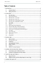
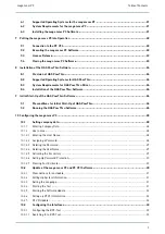
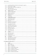
Table of Contents

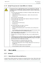
mega macs PC

11.6.1.2

Deleting Entries from the Car History....................................................................................... 78

11.6.1.3

Deleting Single Entries and the Entire Car History ...................................................................... 78

11.6.1.4

All Older Than...................................................................................................................... 79

11.6.2

Component help................................................................................................................... 79

11.6.2.1

Calling Up Component Help.................................................................................................... 79

11.6.3

Service data ........................................................................................................................ 80

11.6.3.1

Calling Up Service Data ......................................................................................................... 80

11.6.4

Timing belt data ................................................................................................................... 82

11.6.4.1

Calling Up Timing Belt Data.................................................................................................... 82

11.6.5

Technical Data ..................................................................................................................... 82

11.6.5.1

Calling Up Technical Data....................................................................................................... 83

11.6.6

Wiring diagrams .................................................................................................................. 83

11.6.6.1

Calling Up Wiring Diagrams.................................................................................................... 83

11.6.7

Fuses/relays........................................................................................................................ 84

11.6.7.1

Calling Up Fuse and Relay Box Images..................................................................................... 84

11.6.8

Component test values.......................................................................................................... 85

11.6.8.1

Calling Up Component Test Values .......................................................................................... 85

11.6.9

Flat rate units ...................................................................................................................... 85

11.6.9.1

Calling Up Flat Rate Units ...................................................................................................... 85

11.6.10

Exhaust Emission Data.......................................................................................................... 86

11.6.10.1 Calling Up Exhaust Emission Data ........................................................................................... 86

11.6.11

Cabin Air Filter..................................................................................................................... 86

11.6.11.1 Calling up the Removal Instructions for the Cabin Air Filter.......................................................... 86

11.6.12

Recall campaigns ................................................................................................................. 87

11.6.12.1 Calling Up Recall Campaigns .................................................................................................. 87

11.6.13

Battery management ............................................................................................................ 87

11.6.13.1 Calling Up Battery Management .............................................................................................. 87

11.7

OBD .................................................................................................................................. 88

12 Applications...................................................................................................................................... 89

12.1

Calculator.......................................................................................................................... 89

12.1.1

Activating the Calculator........................................................................................................ 89

12.2

Pass Thru .......................................................................................................................... 89

12.2.1

Calling Up PassThru.............................................................................................................. 89

12.3

Calculations ....................................................................................................................... 89

12.3.1

Calling Up Calculations .......................................................................................................... 89

12.4

Cost estimate..................................................................................................................... 90

12.4.1

Performing Cost Estimates .................................................................................................... 90

12.5

E-mail ............................................................................................................................... 91

12.5.1

Sending an E-Mail to Hella Gutmann Support ............................................................................ 91

13 Optional HGS Tools............................................................................................................................ 92

13.1

Battery Diagnostics ............................................................................................................ 92

6

Summary of Contents for mega macs PC

Page 1: ... HBMMPCV5400EN0818S0 460 987 91 08 18 User Manual en mega macs PC Original User Manual ...

Page 2: ...e Modifications 14 2 2 1 4 Waiver of the Use of Safety Relevant Software Modifications 14 2 2 2 Non Liability 14 2 2 2 1 Data and Information 14 2 2 2 2 Burden of Proof on the User 15 2 2 3 Data Protection 15 2 2 4 Documentation 15 3 Device Description 16 3 1 Delivery Contents 16 3 1 1 Checking Delivery Contents 16 3 2 Intended Use 17 3 3 Using the Bluetooth Function 17 3 4 Range of Functions 17 3...

Page 3: ...ions for Initial Start Up of HGS PassThru 26 9 2 Running the HGS PassThru Software 26 10 Configuring the mega macs PC 28 10 1 Setting company data 28 10 1 1 Entering Company Data 28 10 1 2 User name 28 10 1 2 1 Entering the User Name 28 10 1 2 2 Assigning a Password 28 10 1 2 3 Deleting the Password 29 10 1 2 4 Deleting the User Name 29 10 1 2 5 Activating the Car History 29 10 1 2 6 Setting Up Pa...

Page 4: ...onfiguring the Car History 38 10 6 2 1 Automatic Car History Transfer 38 10 6 2 2 Manual Parameter Management 39 10 6 2 3 Sending the Car History 39 10 6 2 4 Parameter Management 39 10 6 2 5 Displaying Error Logs 40 10 6 3 Setting the Resolution 40 10 7 Contracts 40 10 7 1 Retrieving the License 40 10 7 2 Displaying the GTC 40 10 7 3 Displaying Other Licenses 41 10 8 Test Functions 41 10 8 1 Preco...

Page 5: ...BD diagnostics 59 11 4 1 Performing an OBD Diagnostics Quick Start 59 11 5 Diagnostics 60 11 5 1 Preparing Vehicle Diagnostics 60 11 5 2 Trouble codes 62 11 5 2 1 Reading Out Trouble Codes 62 11 5 2 2 Deleting Trouble Codes in Vehicle System 63 11 5 2 3 Global Check Reading Trouble Codes 63 11 5 2 4 Global Check Trouble Code Clearing 65 11 5 3 Parameters 65 11 5 3 1 Reading Out Parameters 65 11 5 ...

Page 6: ... 8 1 Calling Up Component Test Values 85 11 6 9 Flat rate units 85 11 6 9 1 Calling Up Flat Rate Units 85 11 6 10 Exhaust Emission Data 86 11 6 10 1 Calling Up Exhaust Emission Data 86 11 6 11 Cabin Air Filter 86 11 6 11 1 Calling up the Removal Instructions for the Cabin Air Filter 86 11 6 12 Recall campaigns 87 11 6 12 1 Calling Up Recall Campaigns 87 11 6 13 Battery management 87 11 6 13 1 Call...

Page 7: ...y Test 93 13 1 3 Preconditions for Saving Test Results in the Car History 93 13 1 4 Saving Test Results in the Car History 93 14 General Information 95 14 1 PassThru Troobleshooting 95 14 2 Troubleshooting 96 14 3 Care and Maintenance 96 14 4 Disposal 96 14 5 Technical Data of the PC VCI 97 7 ...

Page 8: ... PC and PC VCI software When working with the mega macs PC and the PC VCI software it is recommended to read the individual work steps in the manual again to prevent hazard of persons and equipment or operating errors The mega macs PC and the PC VCI software shall be used exclusively by qualified persons Information and knowledge included this training is not explained in this user manual The manu...

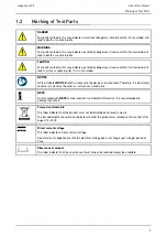
Page 9: ...ed NOTICE refer to a hazard in the device or environment Therefore it is absolutely necessary to observe the notes or instructions stored here NOTE Texts marked with NOTE contain important and helpful information It is recommended to observe these texts Crossed out waste bin This label indicates that the product must not be discarded as domestic waste The bar underneath the waste bin indicates whe...

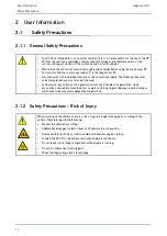
Page 10: ...afety precautions must also be followed Furthermore pay attention to all general instructions from labor inspectorates trade associations and vehicle manufacturers as well as all laws legal ordinances and instructions which have to be commonly obeyed by a repair shop 2 1 2 Safety Precautions Risk of Injury When working on the vehicle there is a risk of injury through rotating parts or rolling of t...

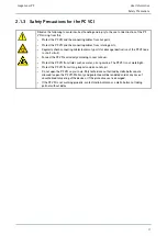
Page 11: ...uction of the PC VCI due to short circuit Connect the PC VCI exclusively according to user manual Protect the PC VCI from fluids such as water oil or gasoline The PC VCI is not watertight Protect the PC VCI from strong impacts and do not drop it Do not open the PC VCI on your own Only technicians authorized by Hella Gutmann are allowed to open the PC VCI Warranty and guarantee will be rendered voi...

Page 12: ...voltage via the building s mains supply can cause severe injury or even death if adequate care is not taken Therefore regard the following Only use power supply cables with grounding contact Only use a checked or the attached power cord Always use the original cable set Regularly check cables and adapters for damage Perform any assembly work such as the connection of the PC VCI to the vehicle or t...

Page 13: ...ummy plugs covering caps or insulating tape with the corresponding warning notice Check the de energized state with a voltage tester Even with disconnected high voltage system residual voltage can still be present Ground and short circuit the high voltage system necessary only if voltage is higher than 1000 V Voltage below 1000 V Cover the parts which are close to the system or which are energized...

Page 14: ... unambiguously Reading out is not possible due to data loss The user does not have the related training and knowledge necessary In these cases the user is not allowed to change programs configurations or to make other changes in the safety system To avoid any danger the user has to contact an authorized dealer instantly Only an authorized dealer can guarantee the safe function of vehicle electroni...

Page 15: ...ice describe the most common fault reasons However there are often further reasons for existing faults which cannot be listed here or there are further sources of error which are unknown yet The Hella Gutmann Solutions GmbH is not liable for failed or unnecessary repair work The Hella Gutmann Solutions GmbH does not accept any liability for the usage of data and information that are found to be in...

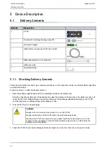
Page 16: ...mpleteness based on the delivery slip Should you identify any damage to the package then open the package in the presence of the delivery service and check the PC VCI for hidden damage Any transport damage to the package supplied and damage to the PC VCI shall be registered in a damage report by the delivery service 2 Take the PC VCI out of the packaging CAUTION Danger of short circuit due to loos...

Page 17: ...al environments e g in commercial areas or in the centre of a town radio interference suppression measures may need to be taken 3 3 Using the Bluetooth Function The terms of use of the Bluetooth function may be restricted or prohibited through law or corresponding legal regulations in certain countries Observe the provisions in force in the respective country before using the Bluetooth function 3 ...

Page 18: ... ED D LED switched off LED switched off Software inactive faulty No voltage present PC VCI faulty LED flashes quickly 1x per sec LED switched off Update failed Update invalid PC VCI faulty LED flashes slowly every 3 sec LED switched off Update failed Update invalid PC VCI faulty LED flashes slowly every 3 sec LED permanently on with regular brief interruptions PC VCI ready for operation 18 ...

Page 19: ... provided by Hella Gutmann the device requires a permanent online connection and the installed driver package Hella Gutmann Drivers To keep the connection costs down Hella Gutmann recommends a DSL connection and a flat rate 1 Install the Hella Gutmann Drivers on the office or repair shop PC The driver package Hella Gutmann Drivers program is on the supplied HGS data carrier 2 Connect the device to...

Page 20: ...ading deleting trouble codes Parameter readout Actuator tests Service reset Basic settings Codings Test function 5 2 Additional Functions and Contents Depending on the License Type Vehicle information e g Timing belt data Service data Recall campaigns 2 updates per year e g Diversification of the existing functions by new vehicle models 20 ...

Page 21: ... The USB drive mega macs PC opens automatically 3 Click Open folder and start the file mega_macs_pc exe You can also open the USB drive as follows Start My Computer mega macs PC The mega macs PC Setup window appears 4 Select the required language and click OK The selection will be saved automatically 5 Click Next A selection window appears A target directory for the mega macs PC software files is ...

Page 22: ...VCI This requires the mega macs PC software to be connected to the PC VCI via USB cable A Bluetooth connection is sufficient when starting up in the future Proceed as follows to execute the mega macs PC software 1 Connect the PC and the PC VCI with the USB cable 2 Go to Start All programs Hella Gutmann Solutions mega macs PC and select mega macs PC The mega macs PC can also be executed as follows ...

Page 23: ...r to the first start up Proceed as follows to connect the mega macs PC software with the HGS server 1 Select Contracts under Settings in the main menu 2 Select License 3 Call up My licenses with Data download is in progress Purchased licenses are displayed 4 Start the mega macs PC software again Now you can work with the mega macs PC software 7 4 Closing the mega macs PC Software Proceed as follow...

Page 24: ...n of the software varies depending on the manufacturer The following options are available Download the PC software Request the PC software on CD or DVD Online solutions Here charges may accrue depending on the manufacturer e g for Registration Licenses Software The software content scope of information and function varies depending on the manufacturer Some manufacturers provide the legally requir...

Page 25: ... target directory 7 Click the PassThru setup exe in the target directory The window HGS PassThru Setup is displayed 8 Select the requested language with 9 Confirm the selection with OK The selection is saved automatically The setup wizard of HGS PassThru is displayed 10 Click Next The general terms and conditions GTCs appear 11 Read the GTCs and confirm them at the end of the text 12 Click Next Se...

Page 26: ... is no lower than 12 V A voltage drop may lead to the abortion of the download and the ECU may be damaged The old software version of the ECU cannot be re established if an update is intended Proceed as follows to run the HGS Pass Thru software 1 Select Applications PassThru in the main menu The disclaimer is displayed 2 Read the disclaimer and confirm it at the end of the text The PassThru functi...

Page 27: ...e requested language 10 Start the communication test with Start test The communication test is started Connection between laptop tablet and HGS VCI is tested The connection between laptop tablet and HGS VCI is active if the left row of arrows is green The connection between HGS VCI and vehicle is tested afterwards The connection between HGS VCI and vehicle is active if the right row of arrows is g...

Page 28: ...Repeat steps 3 5 for further entries 10 1 2 User name 10 1 2 1 Entering the User Name Here you can manage the different users The respective user name is saved for all data stored in the Car History This enables quicker identification of the mechanic who performed the repair work if a query is subsequently made Proceed as follows to enter the user name 1 Select Company under Settings in the main m...

Page 29: ...n prompt 6 Confirm the confirmation prompt with Password will be deleted 10 1 2 4 Deleting the User Name Proceed as follows to delete the user name 1 Select Company under Settings in the main menu 2 Select User 3 Select the required user name 4 Delete the user name with 5 Observe the confirmation prompt 6 Confirm the confirmation prompt with The user name is deleted 10 1 2 5 Activating the Car His...

Page 30: ...ssword and confirm by entering it again 5 Observe the warning notice and confirm The device can now be accessed only with the selected password 10 1 2 7 Creating Cost Estimates Here you can enter the base values for the cost estimate You can enter 3 different hourly rates net and one VAT rate These values are used to calculate the total amount of the work to be done Proceed as follows to enter the...

Page 31: ... Here you can find information including the software and hardware version and the device number 10 2 3 Setting the Language Here you can set the language version if the software is multilingual After having set the language the update will be installed in this language Proceed as follows to set the language 1 Select Update under Settings in the main menu 2 Select System 3 Open the list under Lang...

Page 32: ...hat will then be downloaded and installed The mega macs PC software will be finished automatically upon a successful software update The installation will be checked automatically after startup 10 2 6 Calling up PC VCI Information Here you will find all information required for the identification of the PC VCI Proceed as follows to call up the PC VCI information 1 Select Update under Settings in t...

Page 33: ...infos and instructions with The PC VCI update will be started Data is copied from the mega macs PC software to PC VCI The message PC VCI update successfully done appears if the update was successful 10 3 Configuring the Interfaces Here you can configure the interfaces for the printer and the BPC Tool All interfaces of the mega macs PC software are configured under Settings Interfaces 10 3 1 Config...

Page 34: ...BPC Tool to the battery 2 Select Interfaces under Settings in the main menu 3 Select BPC NOTICE Insufficient voltage supply System data loss Do not switch off the PC and the BPC Tool during the update and do not disconnect both from voltage supply Ensure sufficient voltage supply 4 Start BPC Tool update with 5 Regard the window with infos and instructions 6 Confirm the window with infos and instru...

Page 35: ...ter the requested height of the margins in mm 8 Confirm your entry with The input will be saved automatically 9 Repeat steps 5 8 for further entries 10 Where necessary activate the check box Blank out company logo to print out results without the company logo of Hella Gutmann This function enables hard copy printouts on printed paper Now you can start printing via PC 10 4 Setting the Country Confi...

Page 36: ...e corresponding language The selection will be saved automatically 10 4 3 Setting the Currency Here you can set the prevailing currency Proceed as follows to set the currency 1 Select Country under Settings in the main menu 2 Open the list under Currency with The compilation of currencies depends on the prevailing software 3 Select the requested currency The selection will be saved automatically 1...

Page 37: ...no real values Proceed as follows to set the demo mode 1 Select Miscellaneous under Settings in the main menu 2 Select Miscellaneous 3 Open the list under Demo mode with 4 Select on or off Demo mode is switched off or on 10 6 1 2 Setting Tips Here you can activate or deactivate additional information on different functions Proceed as follows to set the indication of tips 1 Select Miscellaneous und...

Page 38: ...in the main menu 2 Select Miscellaneous 3 Start Factory reset with 4 Observe the confirmation prompt 5 Confirm the confirmation prompt with The mega macs PC software will be automatically reset to the condition at delivery 10 6 2 Configuring the Car History This menu provides the diagnostic results to the present vehicle from the functions Trouble codes Parameters Basic settings and Codings This h...

Page 39: ...he Car History Here you can send the Car History to Hella Gutmann Proceed as follows to send the Car History data 1 Select Miscellaneous under Settings in the main menu 2 Select Car History 3 Send Car History with The Car History is sent to Hella Gutmann 10 6 2 4 Parameter Management NOTE The menu point Parameter management can be done only if Manage parameters manually is set to on With the Param...

Page 40: ...equested resolution 5 Regard the window with infos and instructions 6 Close the window with infos and instructions with The selection will be saved automatically The mega macs PC software will be started again 10 7 Contracts Here you can see the general terms and conditions as well as the licenses and notes of the programs and functions used by the Hella Gutmann Solutions GmbH 10 7 1 Retrieving th...

Page 41: ... the test functions Voltage supply of the PC VCI through power adapter and mains cable is ensured The PC VCI is connected with USB cable and PC The PC VCI is not inserted in the vehicle s diagnostic connector 10 8 2 Performing the VCI Plug Test This test serves as a function check for defects in the PC VCI Proceed as follows to perform the test functions 1 Select Test functions under Settings in t...

Page 42: ...rt circuit and voltage peaks when connecting the PC VCI Danger of destruction of automotive electronics Switch off ignition before connecting the PC VCI to the vehicle 3 Connect the PC VCI to the vehicle s diagnostic connector Both LEDs of the PC VCI flash The PC VCI is ready for operation 4 Start VCI diagnostics Bluetooth with The Wireless diagnostics window appears The Bluetooth function will be...

Page 43: ...form the following functions Start the selected function Confirm the present entry Confirm your menu selection Cancel Cancel the following functions Active function Input Start Start a function or procedure Delete Delete data or entries Arrow keys Navigate with the cursor in menus or functions Print Print the current window Help Open the user manual and explanations on the individual menus or func...

Page 44: ...Sy ym mb bo ol ls s D De es si ig gn na at ti io on n Selection window Open a selection window Select all Select all available elements Unselect all Unselect all available elements Zoom in Zoom in the present view Zoom out Zoom out of the present view 44 ...

Page 45: ... the following information Quantity Component name Manufacturer Item number The shopping cart symbol is dark if there are spare parts in the cart Order network This network is used for data exchange between the mega macs PC and order network Printer Printer is ready for operation Black symbol Printer is ready Symbol flashes green black Print job is in progress Red symbol Connecting error between p...

Page 46: ...vehicle specific ECU diagnostics e g Trouble code readout Parameter readout Codings Vehicle Information Here you can find information regarding the selected vehicle e g Assistance in finding the installation location of a component Timing belt and service data Technical Data Wiring diagrams Recall campaigns of vehicle manufacturers and importers Applications Useful applications are stored here Cal...

Page 47: ...st of saved diagnostic data records on a certain vehicle VIN identification Read out the VIN of the vehicle using the OBD plug OBD diagnostics Here you can only start the OBD diagnostics by selecting the vehicle manufacturer and the fuel type Page forward Go one page forward Page back Go one page back Information Call up additional information regarding the selected vehicle e g Vehicle type Engine...

Page 48: ...des in the systems appears Reduce view Here you can close a print preview after a global check of the trouble codes Selection to the right Add available individual parameters to the selected parameters here Selection to the left Relocate single parameters back to the list of available parameters here Select all Relocate all parameters selected back to the list of available parameters Parameter inf...

Page 49: ...tallation instructions for timing belts and timing chains Diagnostic Database This menu contains manufacturer and vehicle specific solutions for various problematic cases All suggested solutions are from the practice and are retrieved from the Hella Gutmann diagnostics database Technical Data Here you can find all of the data required for service and repair work e g Timing marks Wheel alignment da...

Page 50: ...in the Car History Menu S Sy ym mb bo ol ls s D De es si ig gn na at ti io on n Next entry Here you can call up the next entry in the Car History Previous entry Here you can call up the previous entry in the Car History 11 1 6 2 Symbols in the Component Help Menu S Sy ym mb bo ol ls s D De es si ig gn na at ti io on n Search a component Search a certain component by its name in the component help ...

Page 51: ...from the service database Component list Here you can call up a list with context relevant components Additional information Here you can view additional vehicle information about the manufacturer model or type Select service interval Here you can find and select the vehicle specific service intervals of the vehicle Back to flat rate units Here you can return to the general flat rate units and tim...

Page 52: ...iew you can view the section in the zoomed view Component help Here you can find additional information on the selected component e g Wiring diagrams Parts information 11 1 6 6 Symbols in the Fuses Relays Menu S Sy ym mb bo ol ls s D De es si ig gn na at ti io on n Fuses relays for component Here you can view components with fuses relays in the selected fuse box These are sorted alphabetically and...

Page 53: ... see additional work steps that can arise during work here 11 1 6 9 Symbols in the Battery Management Menu S Sy ym mb bo ol ls s D De es si ig gn na at ti io on n Display explanation Here you can call up explanations for the test result and the specialist terms to be used 11 1 7 Symbols in the Applications Menu S Sy ym mb bo ol ls s D De es si ig gn na at ti io on n Calculator Perform general calc...

Page 54: ...l ls s D De es si ig gn na at ti io on n Copy paste Here you can copy text into the clipboard or paste text from the clipboard Insert special characters Use this symbol to insert special characters into the text Select the keypad Here you can select and manage the country specific keypads Manage keypad languages Here you can select language specific and country specific keypads Add keypad to list ...

Page 55: ...he customer name max 10 characters 9 Open the virtual keypad with NOTE If you do not enter a registration number or the customer name the device does not store any data of the current vehicle in the Car History One registration number or customer name can be used for several vehicles 10 Enter the registration number or customer name 11 Click twice to confirm the input The input will be saved autom...

Page 56: ... diagnostic connector Both LEDs of the PC VCI flash The PC VCI is ready for operation 7 Confirm the selection with Data download is in progress Communication with the vehicle is established 8 Regard the window with infos and instructions The message VIN could not be read out appears if the VIN could not be read out 9 Confirm the window with infos and instructions with where necessary 10 Repeat ste...

Page 57: ... country 1 Select Vehicle selection in the main menu 2 Select i 3 Activate the check box for passenger cars for motorcycles or for trucks 4 Select Vehicle search with 5 Select Country specific 6 Open list under Country with 7 Select the requested country The search criteria are adapted on a country specific basis 8 Open the virtual keypad on the first search criterion with 9 Enter the requested va...

Page 58: ...for trucks 4 Select Vehicle search with 5 Select VIN 6 Open the list under Manufacturer VIN with 7 Select the requested manufacturer 8 Open the virtual keypad under VIN at least 1st to 13th digit with 9 Enter the VIN 10 Click twice to confirm the input Data download is in progress The corresponding vehicles are selected from the database A drop down list appears 11 Double click the required vehicl...

Page 59: ...irm the input Data download is in progress The corresponding vehicles are selected from the database A drop down list appears 9 Double click the required vehicle to select The Vehicle data menu appears Here you can enter either the registration number or the customer name max 10 characters 10 Open the virtual keypad with NOTE If you do not enter a registration number or the customer name the devic...

Page 60: ...able too Measured value Here the device indicates the present flat rate units or states of the ECU graphically and alphanumerically Actuators Here you can activate actuators with the help of the ECU Service reset Here you can reset the service interval manually or automatically Basic settings Here you can assign basic setting values to ECUs and actuators Codings Here you can code tasks to actuator...

Page 61: ...g the clutch Risk of injury or material damage Proceed as follows before starting 1 Apply the parking brake 2 No gear is engaged 3 Regard the window with infos and instructions NOTICE Short circuit and voltage peaks when connecting the PC VCI Danger of destruction of automotive electronics Switch off ignition before connecting the PC VCI to the vehicle 4 Connect the PC VCI to the vehicle s diagnos...

Page 62: ...instructions NOTICE Short circuit and voltage peaks when connecting the PC VCI Danger of destruction of automotive electronics Switch off ignition before connecting the PC VCI to the vehicle 2 Connect the PC VCI to the vehicle s diagnostic connector Both LEDs of the PC VCI flash The PC VCI is ready for operation 3 Select Diagnostics Function Trouble codes NOTE The selection of the following possib...

Page 63: ... out trouble codes of a vehicle system Proceed as follows to delete the trouble codes of a vehicle system 1 Perform steps 1 to 13 as described in section Reading out fault codes Page 62 NOTE All trouble codes selected will be irrevocably deleted from the ECU memory after the deletion process Therefore always save the read out data read in the Car History 2 Clear the saved trouble codes from the ve...

Page 64: ...and vehicle type Functions Assemblies Systems Data 4 Select Global check 5 Call up the Information tab 6 Follow the instructions on the screen 7 Call up the ECU overview with 8 Select further sub categories where necessary The device indicates all ECUs installed in the vehicle The device automatically activates all ECUs Deactivate all ECUs with Activate all ECUs with 9 Activate deactivate the requ...

Page 65: ...codes will be deleted 11 5 3 Parameters Many of the on board systems supply digital measured values in the form of parameters for fast diagnostics Parameters indicate the present state or nominal and actual values of the components The device displays the parameters alphanumerically and graphically Example 1 The engine temperature can be within a range of 30 C to 120 C If the temperature sensor re...

Page 66: ...selected manufacturer and vehicle type Functions Assemblies Systems Data 5 Select the requested assembly 6 Regard the warning notice if appears 7 Select the requested system 8 Observe the information and instructions windows 9 Call up the Information tab 10 Follow the instructions on the screen 11 Call up the parameter with 12 Select the OBD plug and system 13 Regard the window with infos and inst...

Page 67: ...rwards 19 Return to the list of parameter selection with 11 5 4 Actuators Use this menu to activate components in electronic systems You are hence able to check basic functions and cable connections of those components 11 5 4 1 Activating the Actuator DANGER Rotating moving parts electric fan brake calliper piston etc Danger of cutting or pinching fingers or device parts Remove the following thing...

Page 68: ... the actuator test with 11 Select the OBD plug and system 12 Regard the window with infos and instructions 13 Confirm the window with infos and instructions with Communication to vehicle is being established 14 Activate the check box for the requested component NOTE If the vehicle offers the automatic actuator test all ECUs and actuators connected to them will be automatically actuated one after t...

Page 69: ... 55 CAUTION Pulling off of the PC VCI when actuating the clutch Risk of injury or material damage Proceed as follows before starting 1 Apply the parking brake 2 No gear is engaged 3 Regard the window with infos and instructions NOTICE Short circuit and voltage peaks when connecting the PC VCI Danger of destruction of automotive electronics Switch off ignition before connecting the PC VCI to the ve...

Page 70: ...ruction of automotive electronics Switch off ignition before connecting the PC VCI to the vehicle 2 Connect the PC VCI to the vehicle s diagnostic connector Both LEDs of the PC VCI flash The PC VCI is ready for operation 3 Select Diagnostics Function Service reset NOTE The selection of the following possibilities depends on the selected manufacturer and vehicle type Functions Assemblies Systems Da...

Page 71: ...ions Proceed as follows to perform the manual basic setting 1 Perform steps 1 to 11 as described in the section Vehicle selection Page 55 CAUTION Pulling off of the PC VCI when actuating the clutch Risk of injury or material damage Proceed as follows before starting 1 Apply the parking brake 2 No gear is engaged 3 Regard the window with infos and instructions NOTICE Short circuit and voltage peaks...

Page 72: ...os and instructions Proceed as follows to perform the automatic basic setting 1 Perform steps 1 to 11 as described in the section Vehicle selection Page 55 CAUTION Pulling off of the PC VCI when actuating the clutch Risk of injury or material damage Proceed as follows before starting 1 Apply the parking brake 2 No gear is engaged 3 Regard the window with infos and instructions NOTICE Short circuit...

Page 73: ...ons with Communication to vehicle is being established Basic settings are made automatically The message Basic setting successfully done appears if the basic setting was successful 11 5 7 Codings Here you can code components and ECUs Codings are necessary if components were replaced or additional functions in an electronic system must be activated 11 5 7 1 Performing Manual Coding Procedures WARNI...

Page 74: ...ch off ignition before connecting the PC VCI to the vehicle 2 Connect the PC VCI to the vehicle s diagnostic connector Both LEDs of the PC VCI flash The PC VCI is ready for operation 3 Select Diagnostics Function Codings NOTE The selection of the following possibilities depends on the selected manufacturer and vehicle type Functions Assemblies Systems Data 4 Select the requested assembly 5 Select ...

Page 75: ...y the parking brake 2 No gear is engaged 3 Regard the window with infos and instructions NOTICE Short circuit and voltage peaks when connecting the PC VCI Danger of destruction of automotive electronics Switch off ignition before connecting the PC VCI to the vehicle 2 Connect the PC VCI to the vehicle s diagnostic connector Both LEDs of the PC VCI flash The PC VCI is ready for operation 3 Select D...

Page 76: ...Working with the mega macs PC mega macs PC Diagnostics The message Coding successfully done appears if the coding process was successful 76 ...

Page 77: ...u indicates the location of the main fuse box the fuse box and the relay box in the vehicle depending on the selection Timing belt data Here you can retrieve the tools required for repairing the timing belt as well as the vehicle specific removal and installation instructions via the Hella Gutmann Drivers Diagnostic Database Here you can retrieve vehicle specific online assistance via the Hella Gu...

Page 78: ...oceed as follows to select a vehicle from the Car History 1 Select Vehicle selection in the main menu 2 Select the Car History tab 3 Double click the required vehicle to select The mega macs PC software switches back to the main menu automatically The vehicle selected appears in the top toolbar 11 6 1 2 Deleting Entries from the Car History Proceed as follows to clear one or more entries from the ...

Page 79: ...Here you can find the components that are installed in the selected vehicle The following are available Components relevant for diagnostics Here you can find the components that are installed in the selected vehicle and relevant for diagnostic work Parts catalog Here you can find the components that are installed in the selected vehicle There are also additional information on the component and yo...

Page 80: ...h cables connected to an ECU plug You will leave the Component help menu when selecting Component test values Return to the Component help with Fuses relays Here you can view the installation position of the main fuse box the fuse box and the relay box as well as the individual fuses You will leave the Component help menu when selecting Fuses relays Return to the Component help with Service data T...

Page 81: ...story 10 Activate the check box for the processed working positions 11 Enter the tire tread depth and the tire pressure under Further points after having done all working positions 12 Open the virtual keypad under mm with 13 Enter the tire tread depth 14 Confirm your entry with 15 Repeat steps 12 to 14 for further entries 16 Open the virtual keypad under bar with 17 Enter the tire pressure 18 Conf...

Page 82: ...uired for removal and installation Removal Instructions This displays text and images for the individual work steps for the removal process Installation instructions This displays text and images for the individual work steps for the installation process NOTE If multiple removal and installation instructions appear these are indicated with numbers e g Removal 1 Removal 2 Installation 1 You need to...

Page 83: ...d at the end of the text Just click to view this information 11 6 6 Wiring diagrams View a vast number of vehicle specific wiring diagrams here 11 6 6 1 Calling Up Wiring Diagrams NOTE You need an online connection to access the wiring diagrams NOTE The selection of the following possibilities depends on the selected manufacturer and vehicle type Functions Assemblies Systems Data Proceed as follow...

Page 84: ... Proceed as follows to call up fuse and relay box images 1 Select Vehicle information in the main menu 2 Select Fuses relays with 3 Select the required fuse relay box The device indicates the fuse box and or the relay box The right hand window displays an overview of the fuse or relay box The top left window indicates the installation position of the fuse or relay box in the vehicle with a red cir...

Page 85: ...uested assembly 4 Select the requested system All components installed in the vehicle are indicated in red font 5 Double click on the required component to select Alternatively you can select the component with and A selection window appears Depending on the selected component the following information is available Parts information Cabin image Wiring diagrams 6 Select the required information Ima...

Page 86: ...retrieve exhaust emission data 1 Select Vehicle information in the main menu 2 Select Exhaust emission data with 3 Select the correct vehicle type The exhaust emission data appear Text marked in blue in the exhaust emission data menu indicates an extra image or text information Just click to it to view this information 11 6 11 Cabin Air Filter Here you can find the removal instructions for the cab...

Page 87: ...nd handling directly to the authorized repair shops manufacturers For reasons of liability the Hella Gutmann Technical Help Line does not provide information on this matter 11 6 12 1Calling Up Recall Campaigns NOTE You need an online connection to access recall campaigns Proceed as follows to retrieve recall campaigns 1 Select Vehicle information in the main menu 2 Select Recall campaigns with Dat...

Page 88: ...D D m mo od de es s a an nd d O OB BD D t te es st ts s Pre test of German exhaust emission analysis Quick test of the exhaust gas relevant parameters of an OBD vehicle This test should be done before the actual exhaust gas emission inspection Readiness code Indication of the type of diagnostic connector Parameters Indication of all emission relevant parameters The number of the available paramete...

Page 89: ...hop PC to the vehicle in the shop 12 2 1 Calling Up PassThru Perform the steps as described in section Executing the HGS PassThru Software to call up PassThru 12 3 Calculations Here you can perform the the following conversions Fuel consumption Piston speed Current power output resistance Conversion of technical units 12 3 1 Calling Up Calculations Proceed as follows to call up calculations 1 Sele...

Page 90: ...t registration with 7 Open the list under Day with 8 Select the day of the first registration 9 Repeat steps 7 and 8 for Month and Year 10 Confirm the selection with 11 Open the virtual keypad under Odometer reading with 12 Enter the odometer reading 13 Confirm your entry with 14 Repeat steps 6 to 8 for the Vehicle safety and emissions inspection date 15 Confirm the selection with 16 Add a new cos...

Page 91: ...e to the Hella Gutmann support 12 5 1 Sending an E Mail to Hella Gutmann Support Proceed as follows to send an e mail to Hella Gutmann Support 1 Select Applications in the main menu 2 Select E mail with 3 Open input window with 4 Open the virtual keypad under Subject with 5 Enter the required subject 6 Confirm your entry with 7 Open the list under Contact person with 8 Select the requested contact...

Page 92: ...power consumer is switched on and switched off Drain Current Import result system test Here you can import the most recent system test into the Car History Battery test Here you can perform a battery test using the BPC Tool The battery state of charge and state of health are tested Import result battery test Here you can import the most recent battery test into the Car History 13 1 1 Performing a ...

Page 93: ...nto the ST3 connector of the BPC Tool with the arrow pointing up 3 Select Optional HGS Tools in the main menu 4 Select Battery diagnostics with 5 Select Battery test 6 Open the list under Battery position with 7 Select In the vehicle or Outside the vehicle 8 Repeat steps 6 to 7 for another selection 9 Open the virtual keypad under Cold cranking amps A with where necessary 10 Enter a value 11 Confi...

Page 94: ...enu 2 Select Battery diagnostics with 3 Select Import result system test or Import result battery test 4 Start the import with 5 Observe the confirmation prompt 6 Confirm the confirmation prompt with The connection to the BPC Tool is established The test results are saved in the Car History 94 ...

Page 95: ...USB cable and plug connectors for damage Insert the USB cable and plug connectors correctly Disconnect the PC VCI from the diagnostic connection of the vehicle Remove the USB cable from the PC VCI Wait approx 2 or 3 sec and then plug in the USB cable into the USB connection of the PC VCI again Insert the PC VCI into the vehicle s diagnostic interface Regard potential Windows messages Repeat the co...

Page 96: ... Check if there is 12 V supply through the vehicle on pin 16 of the PC VCI PC VCI possibly defective Perform a PC VCI wireless diagnostics 14 3 Care and Maintenance Like any device the PC VCI must be handled carefully Therefore regard the following Regularly clean the PC VCI with a mild cleaning detergent Use commercial household cleaning detergents and a moistened soft cleaning cloth Replace dama...

Page 97: ...WEEE reg no DE 25419042 Phone 49 7668 9900 0 Fax 49 7668 9900 3999 Mail info hella gutmann com 14 5 Technical Data of the PC VCI PC VCI Rated current 200 mA Voltage supply 12 15 V 10 Ambient temperature Recommended 10 35 C Working range 0 45 C Dimensions 110 x 50 x 26 mm H x W x D Type of protection IP20 Data transfer rate max 3 Mbit s Frequency band 2 4 GHz Interfaces Bluetooth class 1 Micro USB ...

Page 98: ...TIONS GMBH Am Krebsbach 2 79241 Ihringen GERMANY Phone 49 7668 9900 0 Fax 49 7668 9900 3999 info hella gutmann com www hella gutmann com 20178 HELLA GUTMANN SOLUTIONS GMBH 1 STUECK PIECE S 9XQ 460 987 911 Made in Germany ...

Reviews: