


GST200-2 Intelligent Fire Alarm Control Panel
Installation and Operation Manual
Page 20
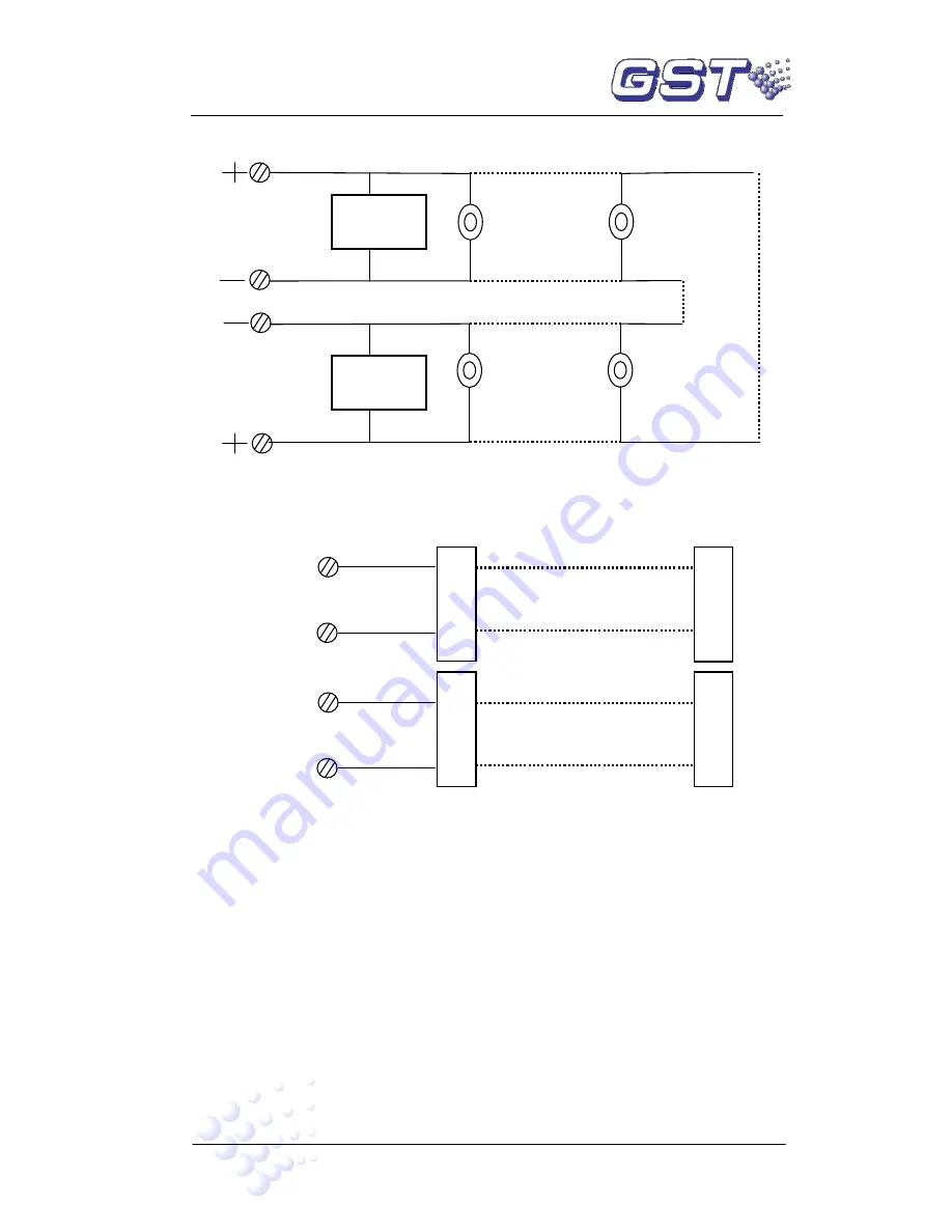
4.4.3.4 Connection of Class A Loop
A Class A loop is shown in Fig. 4-7.
Fig. 4-7
Note: If more than 32 devices are connected to the loop, loop isolators shall be
used and each loop isolator shall not cover more than 32 detectors.
4.4.3.5 Connection of Communication Loop
Fig. 4-8
4.5 Connection Checking and Device Registration
4.5.1 Connection Checking
Check the circuit connected with the FACP. Measure the insulation resistance between
loops and between loops and ground, which should be more than 20MΩ. Measure the
load of detection loops, which should be more than 1kΩ. The resistance between cables
of FIRE ALARM OUTPUT, SOUNDER CIRCUIT OUTPUT and F.P.E. OUTPUT should
be equal to the end-of-line resistance.
4.5.2 Device Registration
Press
SYSTEM
and input commission password. Then press
ENTER
to go to system
setting menu. Then press
ESC
to exit system setting menu, the system enters
commission state (there will be a “-“ at the right bottom of the screen). Rebooting the
LOOP OUT
(XT4)
LOOP IN
(XT2)
Addressable
Field Devices
Addressable
Field Devices
Loop
Isolator
Loop
Isolator
Maximum 32 FACPs
B
A
Network
(XT11)
Maximum 10 Repeater Panels
B
A
Repeater
(XT12)
F
A
C
P
R
e
p
e
a
te
r
P
a
n
e
l
F
A
C
P
R
e
p
e
a
te
r
P
a
n
e
l
Summary of Contents for GST200-2
Page 1: ......