


GST200-2 Intelligent Fire Alarm Control Panel
Installation and Operation Manual
Page 17
Fig. 4-2a
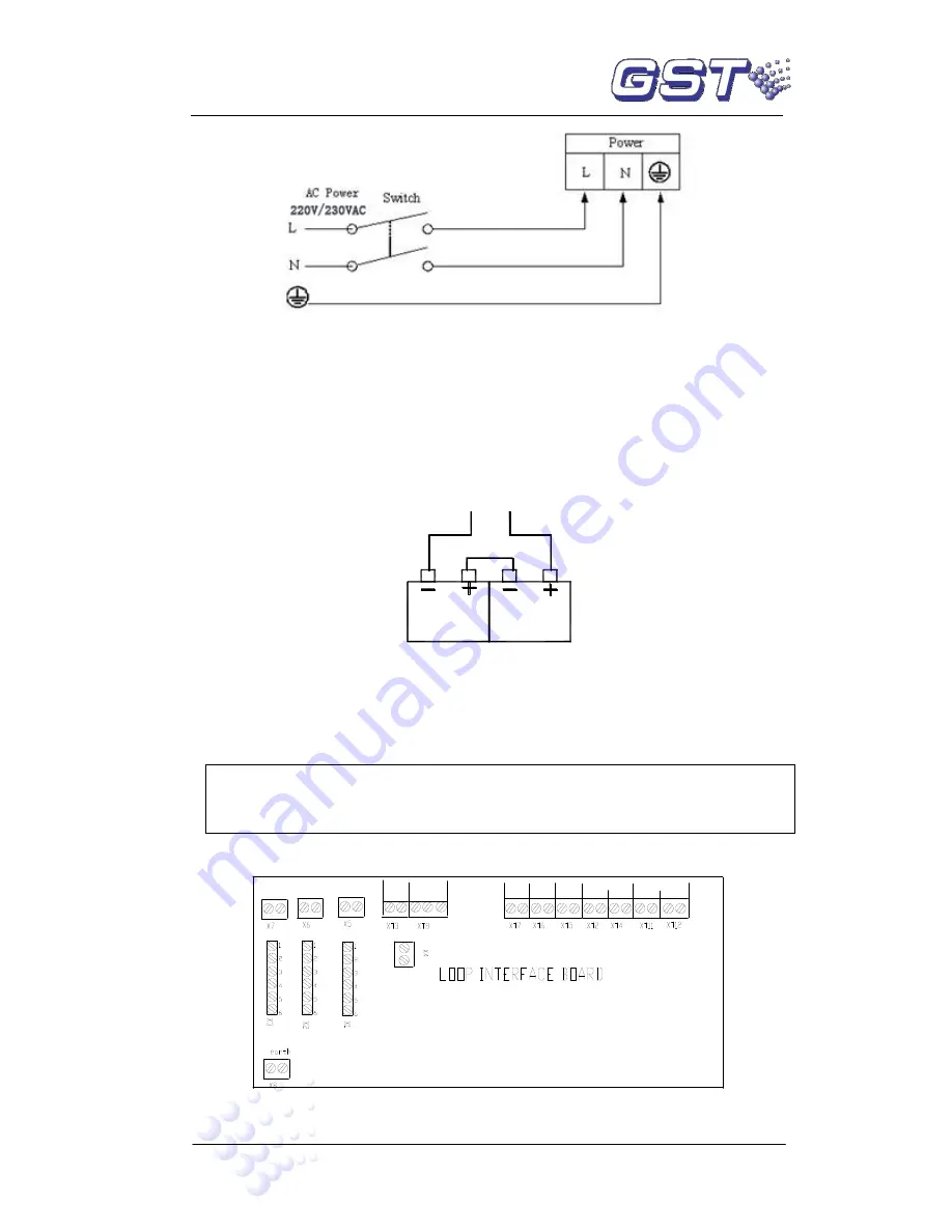
4.4.2 Connection of Batteries
Refer to the Standby Battery Calculations section for the size of the batteries required
for a particular installation.
Connect the batteries according to Fig. 4-2b and then connect with the battery terminal
P4.
P4(+)
P4(-)
Fig. 4-2b
Note: Do not make the final battery connections until the installation is
completed.
4.4.3 Connection of Peripheral Devices
Terminals of loop interface board are shown in Fig. 4-3.
FAULT OUTPUT
NO COM NC
LOOP BUS
LOOP OUT
- +
RS - 485
NETWORK
B A
REPEATER
B A
- +
F.P.E
OUTPUT
LOOP IN
+ -
- +
FIRE
ALARM
OUTPUT
- +
CLASS
CHANGE
SOUNDER
CIRCUIT
OUTPUT
Fig. 4-3
Caution: Do not connect power to your device until you have completed all
input and output connections. Failure to do so may result in injury!
Summary of Contents for GST200-2
Page 1: ......