background image

27

Useful Information

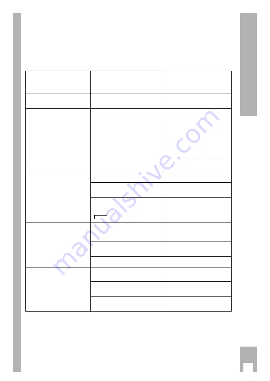
Fixing faults yourself

Not every picture and sound fault means a defect in
your recorder.
Disturbed reception can also be caused by a cable
which is accidentally pulled out, a defect in the TV
set, or failure of the transmitter or the TV aerial
system.

Fault

Cause

Remedy

No clock time indication on the recor-

Mains plug disconnected or defective

Insert mains plug or use a different

der/ the cassette is not pulled in.

contact.

supply socket.

The recorder cannot be operated,

The electronic combination lock is activa-

Deactivate the lock.

the mains voltage supply is o.k.

ted (display »

LOCKED

«).

Recording of TV programmes

Aerial cable not connected.

Connect aerial cable.

not possible (only snow on
the picture screen).

Station to be recorded from is not

Tune to station.

tuned to on the recorder.

Failure of the TV transmitter or

Check by selecting the station to be 

aerial system is defective.

recorded on the TV set or ask your  
neighbour if he can receive this station.

Recording not possible.

The cassette is protected against

Cover the opening at the back of the

new recording.

cassette with adhesive tape.

Timer recording was not carried out.

Timer incorrectly programmed.

For VPS-programmed recordings,
VPS time was entered incorrectly.

The 

¢

ON/OFF

button was not

pressed after an interruption of the
record stand-by mode
(

flashes).

Poor picture quality during

The TV set is not correctly

Correctly tune the TV set to the

playback.

tuned to the transmitting channel

transmitting channel of the recorder.

of the video recorder.

The video heads are dirty.

Have the video heads cleaned by a
specialist.

The video heads are worn.

Contact your dealer.

Operation with the remote control

The batteries in the remote control

Insert new batteries.

is not possible.

are exhausted.

The remote control is not

Point the remote control at

pointed at the recorder.

the recorder.

Incorrect function level set

Switch the remote control to

on the remote control.

the correct function level.

TIMER

Summary of Contents for GV 500 SV

Page 1: ...VIDEORECORDER GV 500 SV...

Page 2: ...15 Entering a stop time 16 Assembling recordings with clean joints 16 TIMER Recording 17 20 The options 17 Programming with the ShowView system variant 1 18 Recorder messages 19 Checking the occupied...

Page 3: ...fields e g loudspeakers KriegimBalkan C C 2h w Do not expose the recorder or the cassette to any moisture The recorder is intended for use in dry rooms If you wish to operate it in the open air make a...

Page 4: ...cable must be inserted in the x socket on the recorder and in the aerial socket on the TV set 3 2 1 3 Connecting Connecting the recorder to the mains Insert the supplied mains cable into the mains so...

Page 5: ...t are required for essential opera ting functions are located on the upper level The buttons that are required for convenience func tions are located on the level under the cover flap 3 6 5 2 1 4 8 f...

Page 6: ...AUDIO COUNTER SAT ED EW VPS C S Switch for selecting the VCR address Buttons for various entries SP LP No function SV V Initiates ShowView programming 1 0 Numbered buttons for various entries g No fun...

Page 7: ...CHECK TIMER SV V PROG STOP DAY START OK 0 9 3 6 8 7 5 2 1 4 AV VPT I N DEX INDEX MARK TRACKING INDEX ERASE Button on the Representation in Function remote control the info table and the dialogue line...

Page 8: ...ady occupied by a TV station In this case proceed as follows Press the i button on the recorder On the TV set search for a channel in the UHF band between the channels 30 and 40 2 channels which is no...

Page 9: ...rogramme positions are available They can be occupied as required with TV stations from the aeri al or a cable connection A number of options are available for tuning 1 By transfer of data from the TV...

Page 10: ...s been completed the TV Station Table appears Pr CH PC DEC 01 C06 ARD OFF 02 C34 ZDF OFF 03 C59 BR3 OFF 04 C40 RTL OFF 05 C36 SAT1 OFF 06 C21 PRO7 OFF 07 C48 WDR OFF GREEN copy sort p o i u CLEAR OK i...

Page 11: ...o i u CLEAR OK i 3 2 1 2 1 Resorting TV stations with the Follow TV function Here the recorder receives the same programme position allocation as the TV set w The recorder and the TV set must be conne...

Page 12: ...of entering the channel number you can enter the frequency of the TV station To do this press the Z VPS red button The display changes from CHANNEL to FREQUENCY Enter the desired frequency as a four d...

Page 13: ...atically switches to the five digit tape length display 2 1 2 EC30 E105 E210 EC45 E120 E225 EC60 E135 E240 E30 E150 E260 E45 E165 E280 E60 E180 E300 E75 E195 E90 E200 p o i u OK i 1 1 w The tape lengt...

Page 14: ...ctions To do this press the T button on the remote control or the S button on the recorder 4 3 2 1 3 2 1 End playback using the H button on the remote control or the i button on the recorder Wind tape...

Page 15: ...started playb ack the recorder adjusts automatically for optimal picture definition 3 2 1 3 2 1 Locating a certain recording Video Index Such System VISS This system allows you to locate the beginnin...

Page 16: ...sing the H button on the remote control or the i button on the recorder Fast forward rewind To do this with the stop function selected press the Y or X button on the remote control or turn the shuttle...

Page 17: ...ly pressing the K button on the remote control or the M button on the recorder max 20 times 600 minutes Changing the stop time If the stop time is to be changed while recording press the K button on t...

Page 18: ...one is to be recorded completely if there is a risk of alterations to timing Example You wish to record the 1st station from 20 15 to 21 45 Uhr and the 2nd station from 21 50 to 22 30 But the programm...

Page 19: ...ct entries are made the CLEAR button can be used to delete the last digit of the ShowView number w The complete ShowView number can be deleted using the SV V button 2 Enter CODE GREEN ED EW 0 9 SV CLE...

Page 20: ...The Record Programming table appears w After an interval the recorder switches the table off automatically and returns to record stand by mode Altering the data of a TIMER position Press the SET CHEC...

Page 21: ...ART STOP po CLEAR OK i 2 1 3 2 1 Programme a new recording To do this press the G button The following appear in the data line a TV station the current date the current time as start time the current...

Page 22: ...nto the recording recorder 4 3 2 1 1 Operation Select programme position for the second recorder or the CD i player To do this press the e button as often as required until A2 appears in the display o...

Page 23: ...numbered buttons 8 5 1 3 and the G button 4 3 2 1 If the recorder receives coded TV programmes from private stations a decoder is necessary Ask your dealer about decoders Connecting Connect the EXT 2...

Page 24: ...recording and operation with a decoder are not possible w To cancel the function repeat the setting starting at step Switch the record stand by setting see step to OFF 3 1 4 3 A2 RECORD PREPARED OFF O...

Page 25: ...r can assist you Deactivating the child lock Press any button The Child lock table appears In place of the code number appears in the table Enter the four digit code number using the numbe red buttons...

Page 26: ...y of each other You can use it with your GV 500 and a second recorder from the series VS 600 to VS 900 and the GV 200 and later models The GV 500 must be adapted in order for the recor ders to respond...

Page 27: ...p o i u OK i 3 2 1 2 1 Remote control of a TV set With this remote control you can also control GRUNDIG colour TV sets that use the remote con trol TP 590 onwards w The functions that can actually be...

Page 28: ...em is defective recorded on the TV set or ask your neighbour if he can receive this station Recording not possible The cassette is protected against Cover the opening at the back of the new recording...

Page 29: ...with E 180 cassette typical 95 seconds 2 Euro AV sockets 21 pole DIN EN 50049 Aerial input socket coaxial B input 75 DIN 45325 Aerial output socket coaxial S output 75 DIN 45325 Supplied accessories R...

Page 30: ...00 46 8 6 29 85 30 GRUNDIG DANMARK A S Lejrvej 19 V rl se 00 45 44 48 68 22 SF 02271 GRUNDIG NORGE A S Glynitveien 25 Postboks 234 Ski 00 47 64 87 82 00 GRUNDIG BELUX N V Deltapark Weihoek 3 Unit 3G Z...

Page 31: ...E P GB 3103 166 12721 GV 500 SV 5251 082 B 3 8...

Reviews: