


20
Communication with a
CU 300 Network via
GENIbus
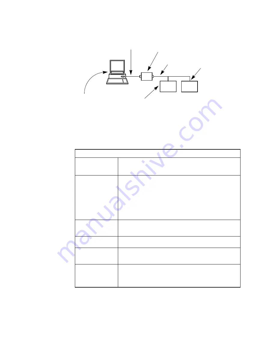
Fig. 12 shows the situation where PC Tool CU 300 communicates with a GENIbus
network consisting of two CU 300 units. It might be that your application is different.
However the procedure in checking the system is general.
If you do not see the correct image of your network in the Operation window - one or
more units might be missing, units appear and disappear or you might not see any
units at all - then go through the following checks.
TM01
7
7
9
4
090
2
Fig. 12
GENIbus network example. The arrows indicate typical causes of communication
problems.
Check table for GENIbus connection
CU 300
• Be sure that the CU 300 units are all switched on.
• Be sure that each CU 300 unit has a unique address (e.g.
number programmed with R100 or with the tool).
GENIbus connec-
tion
• The bus cable must be connected to the right terminals on
the CU 300 unit. The signal wires to A and B and the
screen to Y. Check that the connection to A and B are not
reversed.
• Check for short circuits at the connections.
• Check that the cable is not damaged and that cable con-
nections (if any) are sound. Try to make ohmic measure-
ments.
RS-232/RS-485
GRUNDFOS PC
Tool Link adapter
Study the PC Tool Link instructions.
PC Connection
• At the back of the PC, check to which COM port you have
connected the adapter to and that it is properly fixed.
PC Tool Setup
• In
File | General Tool Setup
check that you are using
GENIbus/RS-232 ‘Connection type’ and the right COM
port.
Windows
• Check in Windows system setting that the COM port you
use is not disabled or configured to a special use.
• Check that there is not another active program on the PC
using the same COM port.
•
Setup of PC tool
•
Windows system setting
PC connect
ion
RS-232/RS-485
GRUNDFOS PC Tool
Link adapter
Unique address
GENIbus
connection
Bus cable
CU 300
CU 300


