


10
Graphic Tool Setup
Having established your connection and having familiarised yourself with the main
screen you are now ready to learn how to customise the tool graphics to fit your phy-
sical application.
Open
File | Graphic Tool Setup
. From this window you can select between a series
of standard applications described in the following table and of communication de-
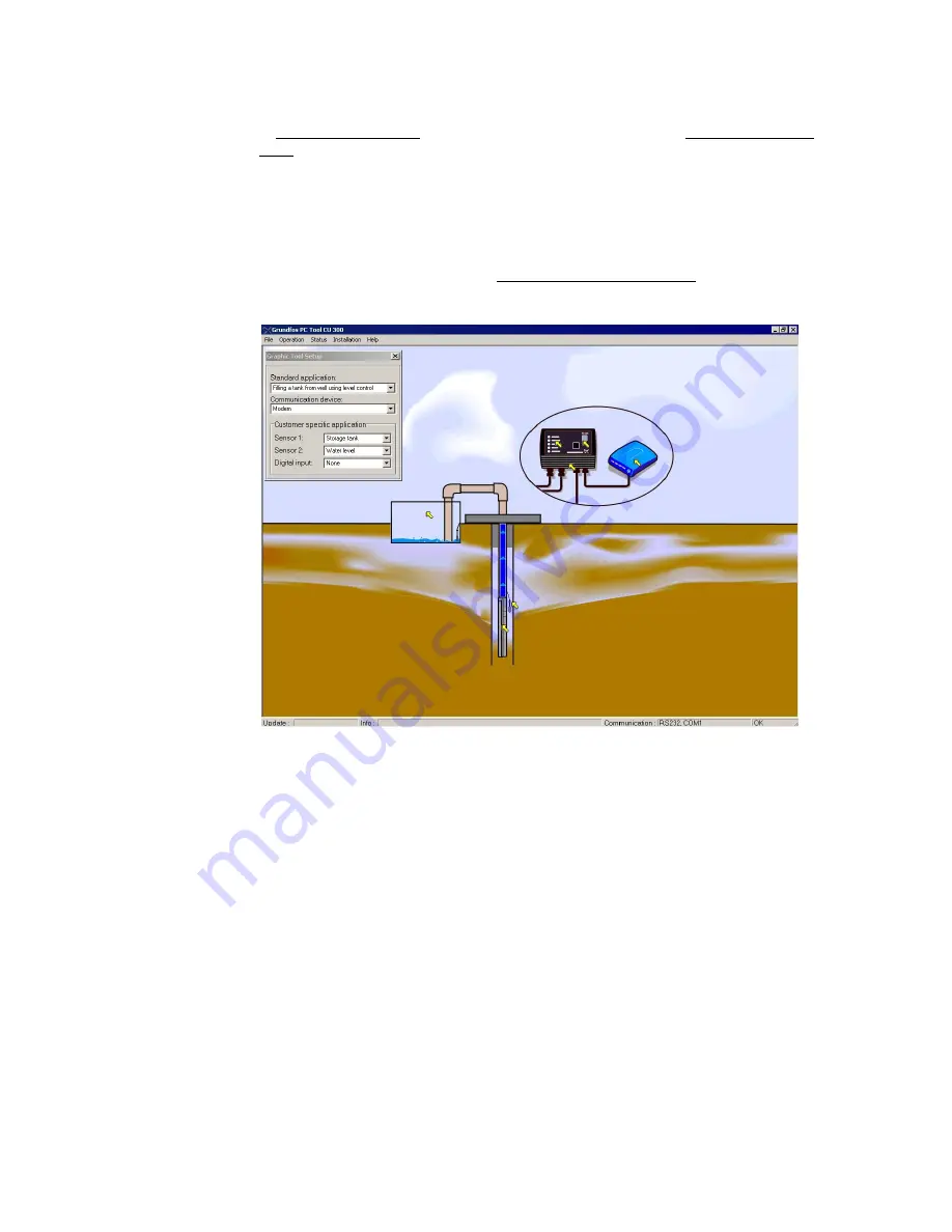
vices. Fig. 4 shows an example where ’Filling a tank from well using level control’ has
been chosen as application and ‘Communication device’ is 'modem'.
Note:
This setup is exclusively visual. It does not change anything in the way the tool
works, the way CU 300 works, the way sensors are scaled etc. It is therefore possi-
ble to misfit the screen appearance to the real system behaviour (e.g. in fig. 4 a mo-
dem is shown connected to CU 300, but in the Status Bar we see that the real
connection is GENIbus). If no standard application fits the real installation the three
sensors can be set up individually (Customer specific application). All options from
the Graphic Tool Setup window can be seen in the table, page 11.
Fig. 4
The window
File | Graphic Tool Setup
for customising the graphics to the use of exter-
nal sensors
TM018
504
0
802


