


Mini-X Installation, Setup & User Manual GRT Avionics
Revision A9 39
Section 5: Primary Flight Display Screen
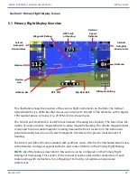
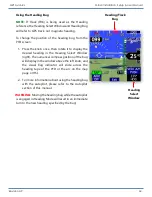
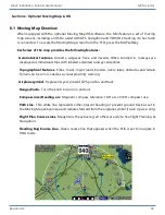
5.1 Primary Flight Display Overview
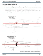
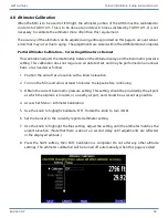
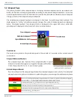
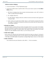
This illustration shows the location of the various flight instruments on the Mini. The Vertical
Speed Indicator is a white bar that moves up and down to the left of the altimeter, with a digital
FPM readout above or below it ( a 70 FPM climb is shown here).
The Mini-B and stock Mini-X use GPS track instead of heading for simplicity. The Mini-X has the
option of using a remote magnetometer to sense magnetic heading. The remote magnetometer
is required for an accurate magnetic heading because the Mini’s location on the instrument
panel will usually have too much electromagnetic interference for precise measurement of
heading.
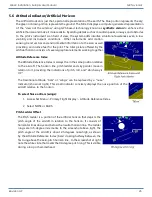
The Mini-X and Mini-AP come standard with synthetic vision, which is the 3D shaded terrain view
with obstacles, runways, waypoint balloons, and course ribbons on the Primary Flight Display.
NOTE:
All of the features described in this section can be configured on the Primary Flight
Display set menu page. This section of the manual provides a description and picture of each
feature along with instructions for configuring it to match your airplane and personal
preferences.
Airspeed
Altimeter
GPS Track
or Heading
Slip-Skid Ball
Altimeter Setting
GPS CDI
Lateral
Autopilot
Annunciators
Vertical
Autopilot
Annunciators
Attitude Bar
Waypoint Balloon
Vertical
Speed
Indicator
Horizon
Line


