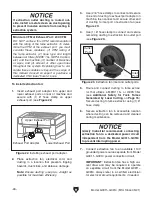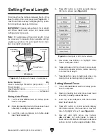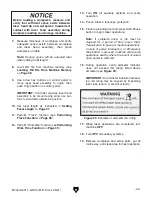
Proximity
Switch
Target
Indicator
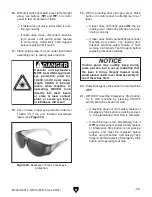
Figure 27. Typical proximity switch components.
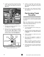
Switch
Lever
Figure 29. Example of typical limit switch lever.
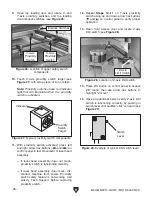
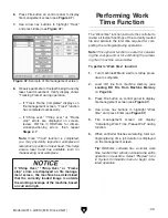
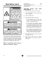
Figure 26. Location of upper safety switch
components.
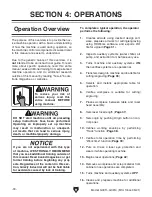
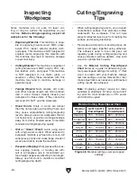
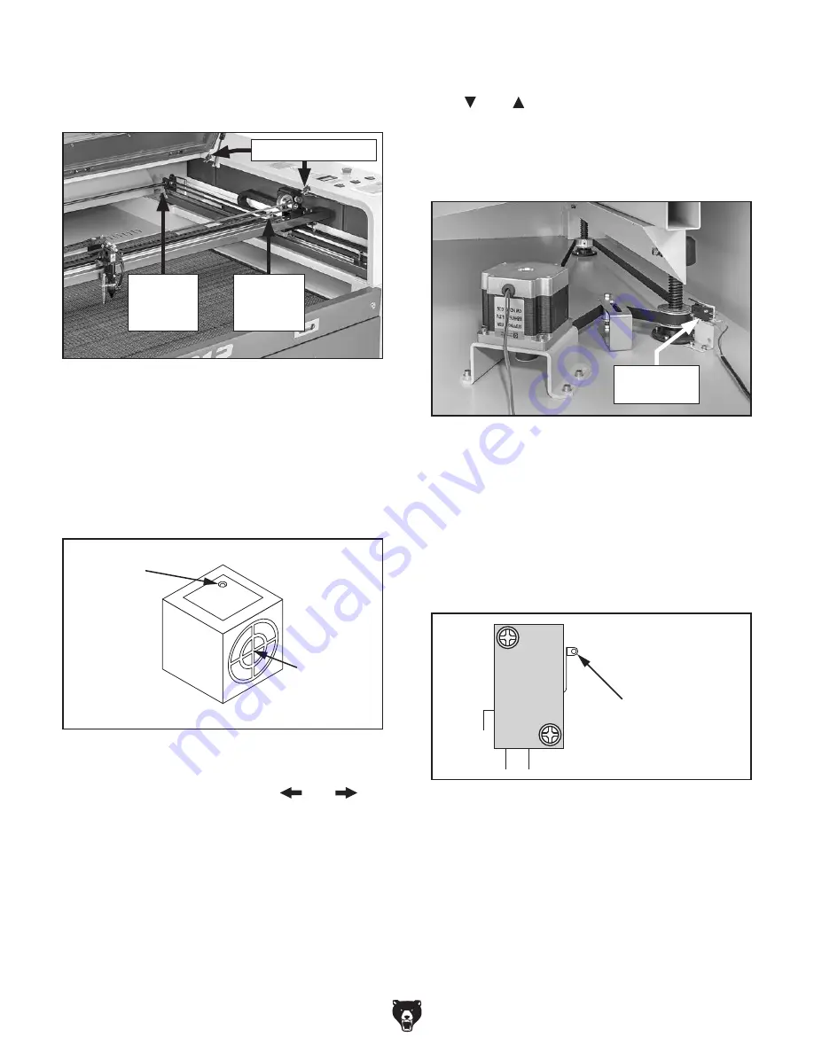
Figure 28. Location of Z-axis limit switch.
-28-
Model G0911–G0914 (Mfd. Since 05/21)
12. Repeat Steps 10–11 on Y-axis proximity
switch using up and down arrow nav buttons
( and ) on control panel to verify proper
operation.
13. Open front access door and locate Z-axis
limit switch (see
Figure 28).
11. With proximity switch activated, press left
and right arrow nav buttons (
and
) on
control panel to test movement of laser head
assembly.
— If laser head assembly does not move,
proximity switch is functioning correctly.
— If laser head assembly does move, dis-
connect machine from power. Proximity
switch safety feature is not working. Call
Grizzly Tech Support before replacing
proximity switch.
10. Touch X-axis proximity switch target (see
Figure 27) with scrap piece of iron or steel.
Note: Proximity switches have red indicator
light that will illuminate when the proximity
switch is activated.
9. Open top loading door and locate X- and
Y-axis proximity switches, and top loading
door interlock switches (see
Figure 26).
Y-Axis
Proximity
Switch
X-Axis
Proximity
Switch
Interlock Switches
14. Press Z/U button on control panel to access
Z/U menu, then use arrow nav buttons to
highlight "Z move".
15. Have an additional person verify Z-axis limit
switch is functioning correctly by pushing in
switch lever until audible "click" is heard (see
Figure 29).
Z-Axis
Limit Switch
Summary of Contents for G0911
Page 100: ......

