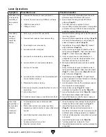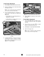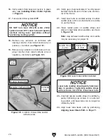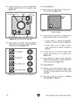
DO NOT turn laser ON with water chiller
system turned OFF. Laser tube will quickly
overheat during laser operations without
functioning cooling system.
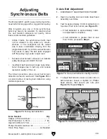
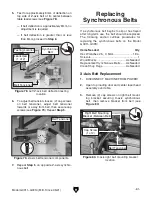
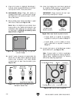
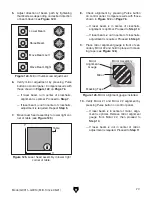
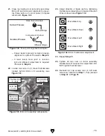
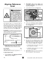
Laser tube saddles should gently hold laser
tube in position. Tightening saddle straps
with excessive force WILL break laser tube.
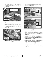
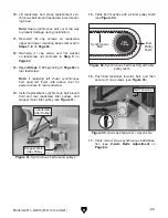
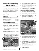
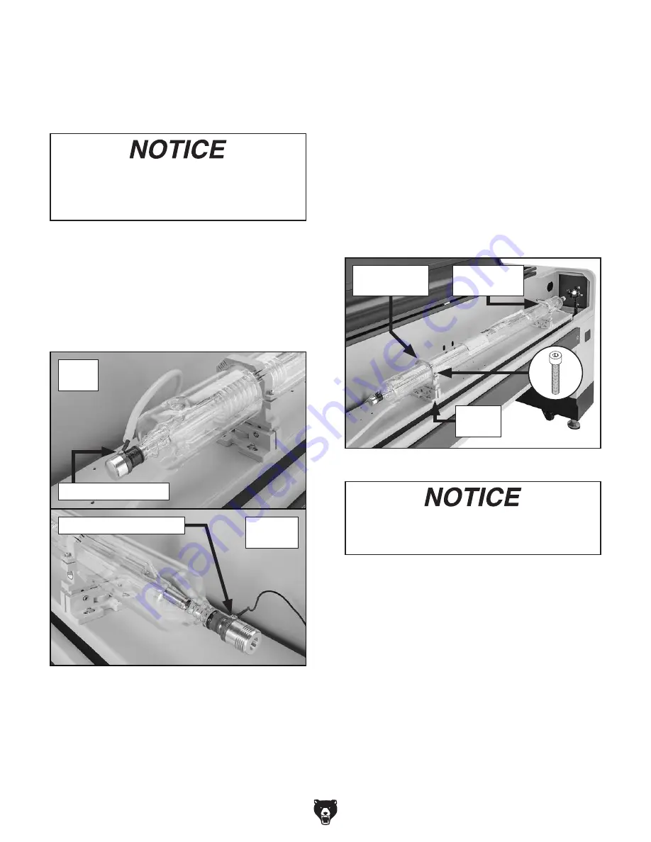
Figure 102. Laser tube saddles installed.
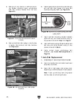
Figure 101. Location of laser tube anode/
cathode wires.
x 4
-70-
Model G0911–G0914 (Mfd. Since 05/21)
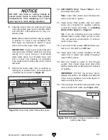
18. Remove any oxidation on terminals with
isopropyl alcohol, then install anode wire on
positive (+) terminal (see
Figure 101).
19. Remove any oxidation on terminals with iso-
propyl alcohol, then install cathode wire on
negative (-) terminal (see
Figure 101).
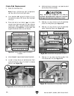
16. Verify water chiller reservoir level is in green
area (see
Installing Water Chiller System
on
Page 23).
17. Turn water chiller system OFF.
20. Verify gap of approximately 6" is still present
between cathode-end of laser tube and cen-
ter of first mirror.
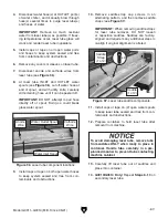
21. Verify laser tube is centered evenly in rubber
saddle pads, and no contaminants are visible
on pad surfaces.
22. Clean rubber pads on saddle straps and
place on laser tube above saddles, as shown
in
Figure 102.
Note: Gap between saddle strap and saddle
may be necessary for proper fit.
23. Carefully secure saddle straps to saddles by
gently tightening cap screws in an alternat-
ing pattern until laser tube can no longer be
rotated by hand.
24. Align laser tube beam path by performing
Aligning Laser Beam Path on Page 71.
Saddle
(1 of 2)
Saddle Strap
(1 of 2)
Rubber Pad
(1 of 6)
Anode
End
Cathode
End
Negative Cathode Wire
Positive Anode Wire
Summary of Contents for G0911
Page 100: ......


