


Model G0887 (Mfd. Since 01/19)
-97-
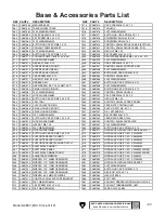
BUY PARTS ONLINE AT GRIZZLY.COM!
Scan QR code to visit our Parts Store.
REF PART #
DESCRIPTION
REF PART #
DESCRIPTION
360
P0887360
MACHINE BASE
414
P0887414
CAP SCREW M8-1.25 X 15
361
P0887361
TABLE WHEEL TRACK
415
P0887415
TOOLBOX
362
P0887362
FLAT WASHER 10MM
416
P0887416
FLAT WASHER 6MM
363
P0887363
CAP SCREW M10-1.5 X 20
417
P0887417
BUTTON HD CAP SCR M6-1 X 12
364
P0887364
SET SCREW M8-1.25 X 12
418
P0887418
SCREWDRIVER PHILLIPS #1
365
P0887365
FLAT WASHER 6MM
419
P0887419
SCREWDRIVER FLAT #1
366
P0887366
BUTTON HD CAP SCR M6-1 X 12
420
P0887420
CONTROL PANEL SWIVEL BASE (BOTTOM)
367
P0887367
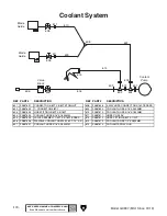
COOLANT PUMP BRACKET
421
P0887421
CONTROL PANEL SWIVEL BASE (TOP)
368
P0887368
FLAT WASHER 6MM
422
P0887422
HEX NUT M8-1.25
369
P0887369
BUTTON HD CAP SCR M6-1 X 15
423
P0887423
SET SCREW M8-1.25 X 15
370
P0887370
COOLANT PUMP 1/8HP 220V 3-PH
424
P0887424
ADJUSTABLE HANDLE M8-1.25 X 25, 57L
371
P0887371
LOCK WASHER 6MM
425
P0887425
FLAT WASHER 8MM
372
P0887372
HEX BOLT M6-1 X 15
426
P0887426
CAP SCREW M8-1.25 X 15
373
P0887373
ACCESS PANEL (FRONT)
427
P0887427
CONTROL PANEL SUPPORT ARM
374
P0887374
ACCESS PANEL (REAR)
428
P0887428
FLAT WASHER 6MM
375
P0887375
ACCESS PANEL (RIGHT)
429
P0887429
BUTTON HD CAP SCR M6-1 X 12
376
P0887376
CAP SCREW M6-1 X 12
435
P0887435
CONTROL PANEL BOX
377
P0887377
HEX BOLT M8-1.25 X 20
436
P0887436
FLAT WASHER 5MM
378
P0887378
GREASE GUN
437
P0887437
BUTTON HD CAP SCR M5-.8 X 12
379
P0887379
HEX WRENCH SET 1.5-10MM 10-PC
438
P0887438
FLAT WASHER 5MM
380
P0887380
SPLASH GUARD (RIGHT)
439
P0887439
BUTTON HD CAP SCR M5-.8 X 12
381
P0887381
FLAT WASHER 8MM
440
P0887440
CONTROL PANEL HANDLE
382
P0887382
LOCK WASHER 8MM
441
P0887441
CAP SCREW M8-1.25 X 25
383
P0887383
BUTTON HD CAP SCR M8-1.25 X 20
442
P0887442
HEX NUT M8-1.25
384
P0887384
DRIP TRAY
443
P0887443
CONTROL PANEL ACCESS PANEL
385
P0887385
CHIP COLLECTION BIN
445
P0887445
FEED-RATE CONTROL UNIT
386
P0887386
SPLASH GUARD (FRONT)
446
P0887446
PHLP HD SCR M5-.8 X 10
387
P0887386
SPLASH GUARD (REAR)
447
P0887447
DIAL EXTENSION
388
P0887388
FLAT WASHER 8MM
448
P0887448
SET SCREW M6-1 X 10
389
P0887389
BUTTON HD CAP SCR M8-1.25 X 20
449
P0887449
FEED-RATE SPEED DIAL
390
P0887390
LOCK WASHER 8MM
450
P0887450
CONTROL PANEL FACEPLATE
391
P0887391
HEX NUT M8-1.25
451
P0887451
FLAT WASHER 5MM
392
P0887392
FLAT WASHER 8MM
452
P0887452
BUTTON HD CAP SCR M5-.8 X 12
393
P0887393
LOCK WASHER 8MM
471
P0887471
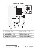
HYDRAULIC REGULATOR LUKU BRV-02G-1
394
P0887394
BUTTON HD CAP SCR M8-1.25 X 20
472
P0887472
HYDRAULIC HOSE 1/4 D X 2200MM
395
P0887395
SUPPORT BRACKET (SHORT)
473
P0887473
HYDRAULIC HOSE 1/4 D X 5800MM
396
P0887396
SUPPORT BRACKET (LONG)
474
P0887474
HYDRAULIC HOSE 1/4 D X 4800MM
397
P0887397
SUPPORT BRACKET W/HOSE CATCH
475
P0887475
HYDRAULIC HOSE 1/4 D X 3200MM
400
P0887400
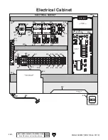
ELECTRICAL CABINET
476
P0887476
HYDRAULIC HOSE 1/4 D X 2900MM
401
P0887401
ELECTRICAL PANEL
477
P0887477
HYDRAULIC HOSE 1/4 D X 900MM, 90-DEG
402
P0887402
ELECTRICAL CABINET DOOR
478
P0887478
HYDRAULIC HOSE 1/4 D X 900MM, 90-DEG
403
P0887403
ADJUSTABLE WRENCH
479
P0887479
HYDRAULIC HOSE 1/4 D X 900MM
404
P0887404
WRENCH 21 X 23MM OPEN-ENDS
480
P0887480
HYDRAULIC HOSE 1/4 D X 2100MM
405
P0887405
WRENCH 17 X 19MM OPEN-ENDS
481
P0887481
HYDRAULIC REGULATOR BRACKET
406
P0887406
WRENCH 14 X 17MM OPEN-ENDS
482
P0887482
FLAT WASHER 6MM
407
P0887407
WRENCH 12 X 14MM OPEN-ENDS
483
P0887483
BUTTON HD CAP SCR M6-1 X 12
408
P0887408
WRENCH 10 X 12MM OPEN-ENDS
484
P0887484
HEX BOLT M16-2 X 75
409
P0887409
WRENCH 8 X 9MM OPEN-ENDS
485
P0887485
HEX NUT M16-2
410
P0887410
CONTROL PANEL SUPPORT BRACKET
486
P0887486
FOOT PAD
411
P0887411
FLAT WASHER 8MM
487
P0887487
COOLANT RESERVOIR DRAIN PLUG M16-2
412
P0887412
CAP SCREW M8-1.25 X 20
488
P0887488
COOLANT THERMOMETER UNIT
413
P0887413
FLAT WASHER 8MM
489
P0887489
WIRED 220V LABEL
Base & Accessories Parts List
Summary of Contents for G0887
Page 108: ......