


-72-
Model G0887 (Mfd. Since 01/19)
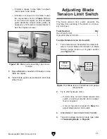
6. Adjust limit switch hex bolt until it just touches
limit switch, then tighten jam nut against ten-
sion limit bracket to secure (see
Figure 112).
Switch should not be depressed.
Figure 111. Blade tension assembly cover and
securing cap screws.
Blade Tension
Assembly Cover
x 4
5. Loosen cap screws that secure blade tension
assembly cover and move it out of the way
(see
Figure 111).
Figure 112. Blade tension limit switch
adjustment components.
Hex Bolt
Jam Nut
Tension Limit
Bracket
7. Install blade tension assembly cover.
8. Connect machine to power and turn blade
tension handwheel
1
⁄
2
turn counterclockwise.
9. Try to start hydraulic motor.
— If motor does not start, blade tension limit
switch is working correctly and no adjust-
ment is required.
— If motor does start, repeat
Steps 4–8 until
hydraulic motor does not start without cor-
rect blade tension.
Adjusting
Downfeed Stop Bolt
If the blade does not travel far enough to complete
the cut, or the blade contacts the vise table, then
the downfeed stop bolt will need to be adjusted.
When the downfeed stop bolt is adjusted, the
downfeed limit switch should be adjusted to match
so the blade and coolant pump stop at the end of
the cut.
Tool Needed
Qty
Open-End Wrenches 17, 30mm ..................1 Ea.
To adjust downfeed stop bolt:
1. Without starting blade, lower headstock all the
way. When headstock stops, blade should be
just below vise table, but not contacting it.
— If blade contacts vise table, raise head-
stock until blade is just below vise table
surface.
2. DISCONNECT MACHINE FROM POWER!
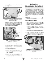
3. Loosen stop bolt jam nut, then adjust
downfeed stop bolt until head of stop bolt con-
tacts bottom of headstock (see
Figure 113).
Figure 113. Downfeed stop bolt adjustment
components.
Jam Nut
Bottom of
Headstock
Downfeed
Stop Bolt
Summary of Contents for G0887
Page 108: ......