


Model G0887 (Mfd. Since 01/19)
-21-
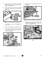
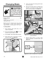
11. Slide support vise guide onto support vise
base shaft (see
Figure 15), then tighten pre-
installed set screw to secure.
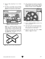
10. Position drip tray on base edge, as shown in
Figure 14.
Figure 14. Drip tray positioned on base edge.
Base Edge
Drip Tray
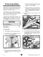
Figure 13. Work stop installed.
Scale
Work Stop Bar
Hole
Figure 15. Support vise guide installed on base
shaft.
Support Vise
Guide
Support Vise
Base Shaft
Figure 12. Foot pad installation components.
Hex Bolt
Hex Nut
Foot Pad
5. Install (1) M16-2 x 75 DOG-PT hex bolt and
M16-2 hex nut at each lag screw hole from
Step 3 (see Figure 12).
6. Place foot pads under hex bolts from Step
5 and lower machine onto foot pads (see
Figure 12).
7. Lower machine so hex bolts from Step 5 rest
on foot pads.
8. Adjust nuts from Step 5 until machine is level.
9. Screw long work stop bar into hole in fixed
outfeed table with scale on bar facing upward,
as shown in
Figure 13.
Lag Screw Hole
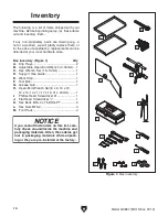
Summary of Contents for G0887
Page 108: ......