


-4-
Model G0887 (Mfd. Since 01/19)
Controls &
Components
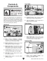
Refer to the following figures and descriptions to
become familiar with the basic controls and com-
ponents of this machine. Understanding these
items and how they work will help you understand
the rest of the manual and minimize your risk of
injury when operating this machine.
Vise Table
Figure 2. Vise table controls and components.
G. Movable Vise Jaw: Holds workpiece against
fixed vise jaw during cutting operations.
H. Vise Lock Handle: Loosen to adjust vise or
tighten to secure its position.
H
G
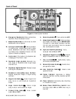
A. Blade Tension Handwheel w/Gauge:
Increases or decreases blade tension. Gauge
ensures accurate tensioning of blade.
B. Blade Guide Scale: Displays position of left
blade guide arm relative to workpiece.
C. Blade Guide Arms: Hold guides that support
blade. Adjust left arm as close to workpiece
as possible to prevent blade from twisting.
D. Coolant Valves (1 of 3): Control flow of cool-
ant through blade guides and onto blade.
E. Work Stop: Provides outfeed scale for repet-
itive cutting operations.
F. Support Vise: Adjusts to provide outfeed
workpiece support.
Headstock
Figure 1. Headstock controls and components.
A
B
C
D
E
F
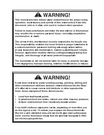
To reduce your risk of
serious injury, read this
entire manual BEFORE
using machine.
I. Blade Speed Dial: Controls blade speed.
Rotate knob clockwise to decrease speed or
counterclockwise to increase speed.
I
Blade Speed
J
J. Master Power ON/OFF Switch: Turns
incoming power
ON and OFF.
Figure 3. Blade speed dial.
Electrical Box
Figure 4. Electrical cabinet power switch.
Summary of Contents for G0887
Page 108: ......