


Model G0887 (Mfd. Since 01/19)
-55-
Figure 87. Hydraulic power unit removed from
base.
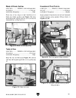
Wood
Blocks
Fill Cap
Hydraulic
Power
Unit
Drain Plug
4. Slide hydraulic power unit out of machine
base and support weight of unit with wood
blocks (see
Figure 87).
5. Remove fill cap (see Figure 87), then remove
drain plug and allow tank to empty into drain
pan.
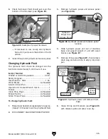
3. Remove hydraulic power unit access panel
(see
Figure 86).
Hydraulic
Power Unit
Access Panel
Figure 86. Hydraulic power unit access panel
location.
7. Install fill cap and hydraulic unit access panel.
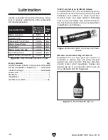
Figure 85. Example of proper fluid level.
Fill Screen
Proper Fluid Level
6. Check fluid level. Fluid should just cover the
bottom of the fill screen (see
Figure 85).
— If fluid level is low, slowly add hydraulic
fluid until it just covers the bottom of the fill
screen.
Changing Hydraulic Fluid
The hydraulic fluid should be changed and the
fluid tank cleaned every 5,000 hours of use.
Item(s) Needed
Qty
T23963 or ISO 32 Equivalent .................... 30 Qt.
Safety Goggles .................................................. 1
Hex Wrench 4, 5mm ....................................1 Ea.
Wood Blocks ..................................... As Needed
5-Gallon Drain Pan ............................................ 1
Open-End or Socket Wrench 13mm ................. 1
Funnel ................................................................ 1
Clean Shop Rags .............................. As Needed
Mineral Spirits .................................... As Needed
Teflon Thread Tape ........................... As Needed
To change hydraulic fluid:
1. Raise/lower headstock repeatedly for approx-
imately 10 minutes to warm up hydraulic fluid.
2. DISCONNECT MACHINE FROM POWER!
6. Clean fill cap and fill screen (see Figure 85)
with mineral spirits and allow to air dry.
Summary of Contents for G0887
Page 108: ......