- 16 -
Description of functions
A l l t r a n s m i t t e r c o n t r o l s c a n b e o p e r a t e d
simultaneously and are fully proportional, i.e.
t h e c o n t r o l s u r f a c e s a c c u r a t e l y f o l l o w t h e
d e f l e c t i o n o f t h e t r a n s m i t t e r s t i c k t o a n y
position between neutral and full travel.The
X-306 FM 35 and X-306 FM 40 radio control
sets are approved for use on the
prescribed spot frequencies (channels) in the
appropriate frequency band, without requiring
r e g i s t r a t i o n o r p a y m e n t o f a f e e . T h i s R C
system can also be operated in situations
where other FM and AM systems are in use,
provided that proper checking of
frequencies is observed.If there are several
modellers at the site, it is essential to check
which channels are in use before you switch
on your own transmitter. If two transmitters
on the same frequency are switched on at
t h e s a m e t i m e , t h e r e s u l t i s a l w a y s
interference.The transmitter and receiver are
designed for use with FMsss plug-in crystals.
The crystals determine the spot frequency
(channel) on which the system operates. It is
essential always to use plug-in crystals fitted
with a protective cap. The crystal fitted to the
t r a n s m i t t e r m u s t b e a r t h e s a m e c h a n n e l
number as the crystal fitted to the receiver.
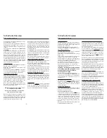
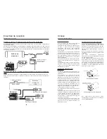
Transmitter controls and functions
(see illustration on right-hand page)
7-section telescopic aerial (1)
Battery indicator (2)
This takes the form of a clear three-stage LED
monitor system with an electronically
expanded scale to monitor the battery voltage. If
the battery indicator moves into the „flat“ range,
cease operations immediately and either fit new
dry cells or recharge the NiCd or NiMH cells.
Transmitter
Description of functions
Transmitter controls and functions
red
yellow green
red
yellow green
red
yellow green
Battery „full“
Battery „half-empty“
Battery „flap“
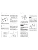
Steering function lever (3)
Steering function trim lever (4)
This very useful lever provides fine adjustment
of the steering function, ensuring that each indi-
vidual model runs perfectly straight at the neu-
tral position.
Charge socket (5)
If the transmitter is fitted with rechargeable cells,
these can be charged via this socket. During the
charge process the ON/OFF switch on the
transmitter must be set to OFF.
Maximum charge current 1 A !!!
+
-
Polarity of the
charge socket
Transmitter crystal (6)
The plug-in crystal is easily accessible from
outside the case, and can be withdrawn together
with the protective cap. Use only genuine
GRAUPNER FMsss plug-in crystals on the
appropriate frequency. They are fitted with a black
protective cap and bear the code letter T (for
transmitter).
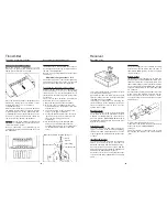
ON/OFF switch (7)
Servo reverse switches (8)
These switches are used to reverse the direction
of rotation of the servos connected to the
receiver. This feature is very useful when setting
up the system to suit a new model.
Throttle servo
Steering servo
normal
reversed
normal
reversed
Transmitter
Controls and functions
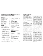
Throttle function neutral switch (9)
The neutral position of the throttle stick
(motor speed control) can be set to either
of two positions using the neutral position
switch. (see illustration below).
Throttle function trim lever (10)
Provides fine adjustment of the throttle
function.
Throttle lever (11)
Transmitter neckstrap lug (12)
Proportional transmitter channel 3 (13)
By means of this transmitter the third channel
being active with the receiver, will be controller
proportinally.
- 17 -
Neutral switch up
Neutral switch down
“THROTTLE“ stick
Forward
Forward
Reverse
Reverse
This setting is suitable for
models equipped with a
controller with centre
detend.
This setting is suitable for
models fitted with glowplug
motors, i.e. the “Stop“
position is nit in the centre.
Stop
Stop
50%
50%
70%
30%
12
1
2
3
4
6
5
7
8
9
10
11
13


