background image

01


      33601 VARIO Modul - Graupner HoTT 2.4


THANK YOU

for purchasing the Graupner HoTT VARIO MODULE. 
If you do not have the Graupner HoTT 2.4 radio system this product will not work. This product is not com-
patible with any other 2.4GHz radio system.
Please read through this entire manual before you attempt the installation and usage of your Graupner 
HoTT SMART-BOX! 

These operating instructions are part of this product. They contains important notes to the operation and 
handling. Please take this into consideration when you pass on the product to third parties. Neglect of the 
operating instructions and the safety instructions lead to expiring the warranty.
Graupner constantly work on the advancement of all remote control systems; changes of the scope of deli-
very in form, technology and equipment we must reserve ourselves therefore. Please have understanding
for the fact that from data and illustrations of this operating instructions no requirements can be derived.

Please keep these instructions for further reference! 

DESCRIPTION

1. 

The Graupner-HoTT VARIO-Module enables the wireless monitoring of the altitude and the graphical and 
acoustic indication of climbing or descent of the model in real time. The VARIO-MODULE can be program-
med directly with all HoTT transmitters with integrated telemetry in the transmitter display (some models 
such as MC-24 with update or modi

fi

 cation).

The following transmitters must be programmed via SMART-BOX order No. 33700:

 mx-12 HoTT order 

No. 4754, mx-16 HoTT order No. 4755, and mx-22 No. 4801/4802, mc-19 No. 4821 and mc-22 No. 4818 
after conversion to HoTT. This differentiation between the transmitter models and the resulting operation is 
explicitly mentioned at the appropriate point in the instructions.

Informations available - Setup: 

Current Altitude, Min. Altitude, Max. Altitude, Climb-/Sinkrate/s, Climb/-Sinkrate/3s, Climb/-Sinkrate/Min., 
Continous Vario, accuracy: 0.1m

Note: 

Any settings you make on the Transmitter or SMART-BOX will be stored in the VARIO-MODULE 

only!

Since the VARIO-MODULE can be updated via the USB connection, you always have the latest software 
and can utilize future functions or languages. Firmware updates for the VARIO-MODULE can be transferred 
via the DATA or telemetry interface in conjunction with a PC running Windows XP, Vista or 7. For this you 
also require the USB interface, Order No. 7168.6, and the adapter lead, Order No. 7168.6A, which are 
available separately.
The programs and 

fi

 les required for this are available from www.graupner.de in the Download area for the 

corresponding products. 

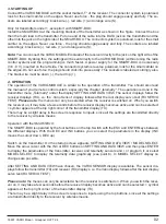
2.  MOUNTING THE SENSOR IN THE PLANE

Mount the sensor at an appropriate location in the model. The sensor detects changes in air pressure and 
calculates the resulting actual altitude. Therefore, make sure that the sensor is wind-protected in the model 
and is not located directly in the 

fl

 ow of the propeller. Likewise, it must not be mounted on an air-tight place, 

such in a sealed radio box. The best way to 

fi

 x the VARIO-MODULE with the mounting tabs or double sided 

tape on a wind-protected frame in the model, the orientation of the sensor is not important.

Note:

 the accuracy of the sensor also varies with alterations in ambient air pressure, e.g. due to sudden 

changes in weather conditions, as well as with changes in air pressure which occur in the course of the day 
or during an extended 

fl

 ight. It is not uncommon for minor 

fl

 uctuations in air pressure to affect the accuracy 

of the sensor to the extent of about 10 to 20 m. These inaccuracies can also be caused by pressure changes 
inside the fuselage itself (e.g. high pressure due to the forced propeller air

fl

 ow, or air 

fl

 owing into the model 

during a 

fl

 ight).

Summary of Contents for HoTT 2.4 VARIO Module 33601

Page 1: ...2 Minimum Altitude 06 4 3 Maximum Altitude 06 4 4 Sink rate sec Negative Difference 1 06 4 5 Sink rate 3 sec Negative Difference 2 07 4 6 Climb rate sec Positive Difference 1 07 4 7 Climb rate 3 sec Positive Difference 2 07 4 9 Display Overview 08 5 Setup Displays 09 5 1 Continous Vario Setup Sensivity 09 6 Telemetry Display SIMPLE DATAVIEW 10 7 Firmware Updates 12 8 Signal Tone Overview 13 9 Warr...

Page 2: ... instructions Informations available Setup Current Altitude Min Altitude Max Altitude Climb Sinkrate s Climb Sinkrate 3s Climb Sinkrate Min Continous Vario accuracy 0 1m Note Any settings you make on the Transmitter or SMART BOX will be stored in the VARIO MODULE only Since the VARIO MODULE can be updated via the USB connection you always have the latest software and can utilize future functions o...

Page 3: ... DATA VIEW The sensor displays follow the receiver displays RX i e the Vario Sensor display follows after the last display servo test RX SERVO TEST Please note the menus can only be selected when the receiver is switched on When you switch the receiver on it may take a few seconds before the receiver display becomes active and can be selected symbol appears at the top right corner of the transmitt...

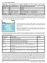
Page 4: ...f the SMART BOX followed by the buttons of the mx 16 HoTT as an example in parentheses Please note that the button layout for example of the HoTT mc transmitters order No 4758 4759 may differ Read the manual of your remote control system to become familiar with the telemetry operation Parameter Description Setup Altitude Current Altitude Meter Min Minimum Altitude since the start Meter Max Maximum...

Page 5: ...00 to 3000 m Max ALT Page 3 Maximum Altitude 500 to 3000 m Negative Difference 1 Sek Page 4 Sink rate Sec 50 0 to 0 m Negative Difference 2 3 Sek Page 5 Sink rate 3 Sec 50 0 to 0 m Positive Difference 1 Sek Page 6 Climb rate Sec 0 to 50 0 m Positive Difference 2 3 Sek Page 7 Climb rate 3 Sec 0 to 50 0 m Warning Time Page 2 page 7 Warning Time OFF 5 10 15 20 25 30 sec Repeat Time Page 2 page 7 Repe...

Page 6: ...warning at any time by pressing one of the buttons on the top of the SMART BOX If you wish to carry out an adjustment point 4 2 to 4 7 you must use the INC or DEC buttons above the screen to select page 1 Save Sensor Simultaneously pressing the INC and DEC buttons SET switches the parameter to be adjusted to inverse video white on black this indicates that it can be programmed pressing the INC but...

Page 7: ... Tone page 2 20m Off Always O 4 3 Maximum Altitude Page 3 Maximum Altitude Maximum altitude of the model during operation warning threshold set between 500 and 3000 m based on the star ting altitude 0 m Factory setting 500 m Signal Tone Z DEC Max Altitude Set Warning Max ALT Warning Time Repeat Time Signal Tone page 3 500m Off Always Z INC 4 4 Sink rate per second Page 4 Sink rate s Negative Diffe...

Page 8: ...starting altitude 0 m Factory setting 10 m Sec Signal Tone N 4 7 Climb rate per 3 seconds Page 7 Climb rate 3 s Positive Difference 2 Climb rate of the model per 3 sec in Meter warning threshold set between 0 and 50 m based on the starting altitude 0 m Factory setting 1 m 3 Sec Signal Tone M DEC Negative Difference 2 Set Warning Diff 3 Sec Warning Time Repeat Time Signal Tone page 5 1 m Off Always...

Page 9: ...Warning Max height Warning Time Repeat Time Signal Tone page 3 500m Off Always B INC DEC Negative Difference 1 Set Warning Diff Sec Warning Time Repeat Time Signal Tone page 4 10 m Off Always C INC DEC Negative Difference 2 Set Warning Diff 3 Sec Warning Time Repeat Time Signal Tone page 5 1 m Off Always B INC DEC Positive Difference 1 Set Warning Diff Sec Warning Time Repeat Time Signal Tone page...

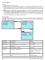
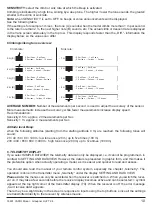
Page 10: ...m sec 1 m sec or 3 m sec Factory setting is 1 m sec You should use one of these at the same time Sensivity Setup Select the User Setup display as shown in the diagram Press the INC and DEC buttons on the SMART BOX resp SET simultaneously and select User Setup page 2 To save the selected settings go back to page 1 and choose Save Sensor YES Parameter Description Setup User Setup User seup 1 2 page ...

Page 11: ...lect SIMPLE DATAVIEW the telemetry data can only be displayed i e it cannot be programmed in contrast to SETTING AND DATAVIEW However the data is represented in graphic form and this makes it the preferable option when actually operating a model as it is easier and quicker to read and assess You should also read the manual of your remote control system especially the chapter telemetry The operatio...

Page 12: ...ursor to AIRPLANE model aircraft or CAR model car then press ENTER SET to move to the corresponding telemetry display In the aircraft display AIRPLANE you can use the INC or DEC button to select one of the following graphic displays RECEIVER shows the same data as RX DATAVIEW RECEIVE VARIO MODUL receive performance actual altitude min and max altitude temperature climb rate sink rate sec climb rat...

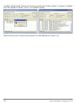
Page 13: ...as shown in the illustrations and are connected Start the Graupner Firmware Update Utility Under COM Port Setup select the cor rect COM port i e the one to which the USB lead is connected If you are not sure of this press the button Search and select in the pop up window Silicon Labs CP210x USB to UART Bridge and press OK Select Baud Rate 19200 Under Interface Type click on Signal 2 Vcc 3 Gnd Now ...

Page 14: ...4 The Status display and the Progress bar show the progress of the firmware update The update is completed when the message Complete 100 or Complete appears Switch off the receiver and disconnect all leads Your VARIO MODULE is ready to use ...

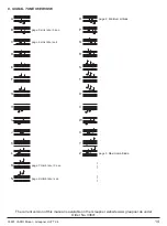
Page 15: ...um altitude O P page 5 sink rate 3 sec page 4 sink rate sek Q R S T U page 7 climb rate 3 sec page 6 climb rate sec V W X Y Z page 3 Maximum altitude 8 SIGNAL TONE OVERVIEW The current version of this manual is available on the Graupner website www graupner de under Order No 33601 ...

Page 16: ...e of it in the or dinary domestic waste The correct method of disposal is to take it to your local collection point for recycling electrical and electronic equipment The symbol shown here which may be found on the product itself in the operating instructions or on the packaging indicates that this is the case Individual markings indicate which materials can be recycled and re used You can make an ...

Page 17: ...a société Graupner GmbH Co KG Henriettenstraße 94 96 73230 Kirchheim Teck Allemagne accorde sur ce produit une garantie de 24 mois à partir de la date d achat La garantie prend effet uniquement sur les vices de fonc tion nement et de matériel du produit acheté Les dom mages dûs à de l usure à de la surcharge à de mauvais accessoires ou à d une application inadaptée sont ex clus de la garantie Cett...

Page 18: ..._____________________________________________________________________________ _____________________________________________________________________________________ _____________________________________________________________________________________ _____________________________________________________________________________________ ________________________________________________________________...

Page 19: ..._____________________________________________________________________________ _____________________________________________________________________________________ _____________________________________________________________________________________ _____________________________________________________________________________________ ________________________________________________________________...

Page 20: ...supplier We accept no liability for printing errors Sous réserve de modifications et de possibilité de livraison Livraison uniquement au travers de magasins spécialisés en modélisme Nous pourrons vous communiquer l adresse de votre revendeur le plus proche Nous ne sommes pas responsables d éventuelles erreurs d impression Con riserva di variazione delle specifiche e disponibilità del prodotto Forn...

Reviews: