


KARRERA K-FRAME — Installation & Service Manual
217
Router Interface
2.
Select the source to be configured with the router on the left scrolling
list.
3.
Touch the Video Input data pad and enter the number of the input that
will be used with the router video destination.
4.
If the routed source will have an associated key signal, touch the
appropriate Key Input button, then touch the Key Input data pad and
enter the number of the input that will be used with the router key
signal destination.
Note
If you assign a key input, the router system needs to be configured to switch
that key destination along with the video destination. Router levels can be
used to accomplish this.
5.
Touch the
Router
type button to identify it as a routed source.
Note
The adjacent status indicator is green when a router is detected, and red
when there is no response. If red, you should check the K-Frame or router
system configuration or the physical Ethernet connections.
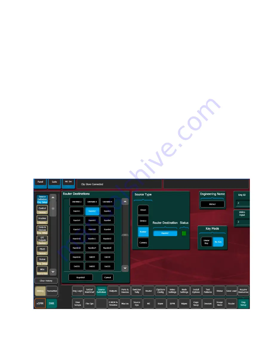
6.
Touch the
Router Destination
data pad to open the Router Destinations
menu. The K-Frame Video Processor receives a list of destination from
the router and displays them on scrolling list on the left (
).
Figure 156. Router Destination Selection Menu
Summary of Contents for KARRERA K-FRAME
Page 12: ...12 KARRERA K FRAME Installation Service Manual Contents ...
Page 30: ...30 KARRERA K FRAME Installation Service Manual Regulatory Notices ...
Page 56: ...56 KARRERA K FRAME Installation Service Manual Section 2 Control Surface Installation ...
Page 266: ...266 KARRERA K FRAME Installation Service Manual Appendix B Field Replaceable Units ...
Page 278: ...278 KARRERA K FRAME Installation Service Manual Index ...


